14
vwr.com I Instruction manual VWR® U Water System
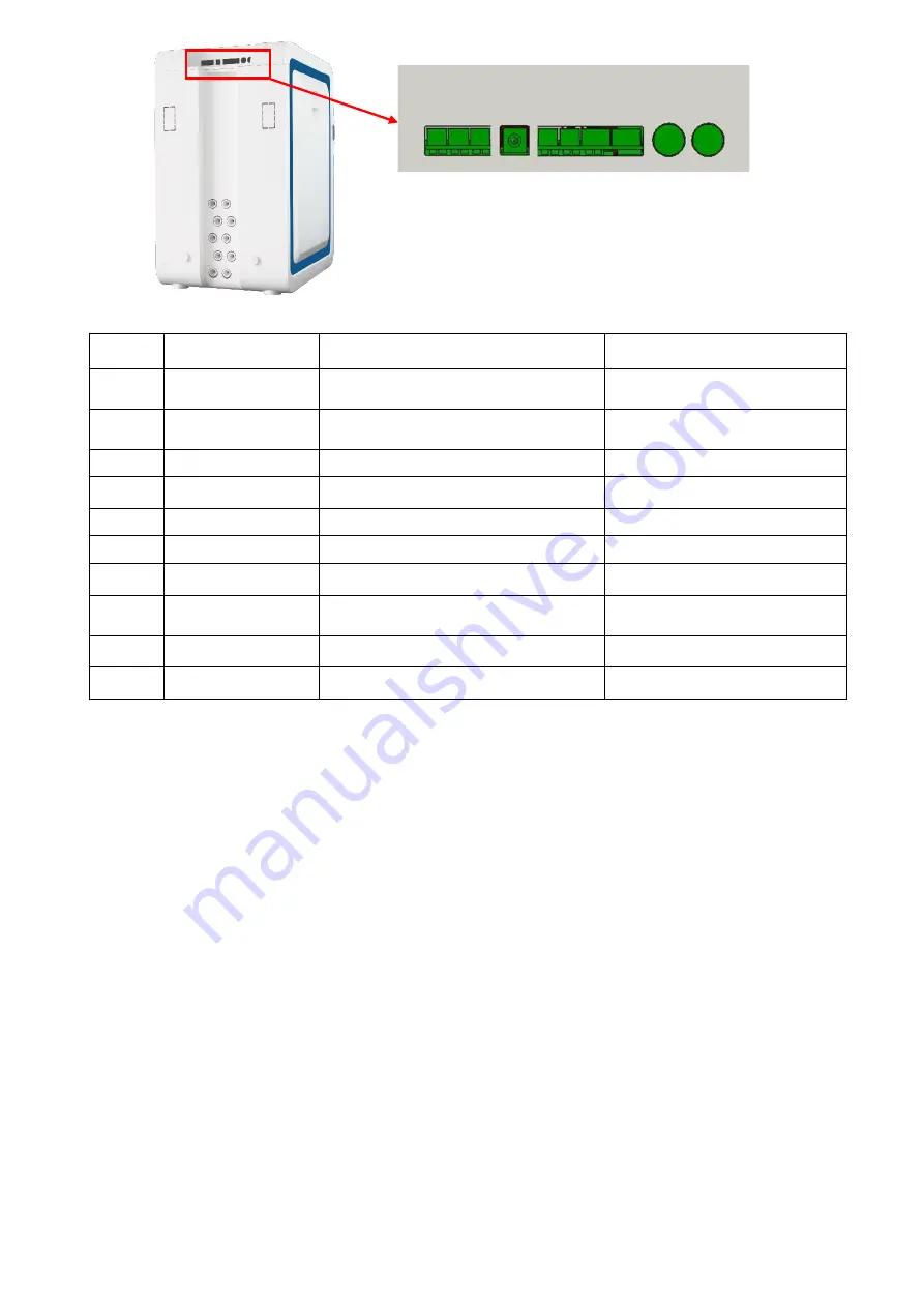
Description of electrical
control board
No.
Label
Description
Connect to
1
Feed Valve
For the feed solenoid valve control
line
Feed solenoid valve
(optional)
2
Tank UV
For the sanitization module control
line
Automatic sanitization
module
3
Feed Pump
For the booster pump control line
Booster pump (optional)
4
Power
Power cord port
Power adapter
5
Prefilter Sensor
For backwash signal line
Prefiltration (optional)
6
Overflow Sensor For overflow sensor signal line
Overflow sensor
7
Leak Sensor
For leak sensor signal line
Leak sensor (optional)
8
Level Sensor
For the pure water tank level
sensor control line
Pure water tank level sensor
9
CAN A
Data cable port
Dispenser or control console
10
CAN B
Data cable port
Dispenser or control console
1
9
8
7
6
5
4
3
2
10


