56
16. Measuring – Current
a) Introduction
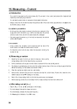
• The current is measured via the current clamp (1). The sensors in the current clamp detect the magnetic field
created by current-carrying conductors.
• You can take measurements on insulated and uninsulated conductors.
• Always ensure that the conductor passes through the centre of the current clamp (pay attention to the marks)
and that the clamp is closed.
Cancellation and Addition
• Do not use the current clamp to surround more than one conductor. If the
supply and return conductors (e.g. L and N) are measured, the currents
will cancel each other out and no measurement will be displayed.
• If several supply conductors (e.g. L1 and L2) are measured, the currents
will be added together.
Low currents
• At low currents, the conductor can be wound around one side of the
current clamp to increase the total measured current.
• To obtain the correct current value, divide the measured current by the
number of coils.
b) Measuring procedure
1. Determine the type of current you intend to measure, then read the
corresponding section in this chapter before you proceed.
2. Set the multimeter to the required current mode as indicated in the corresponding section.
3. The display is automatically set to zero when the current clamp is closed. If there is a strong magnetic field that
affects the reading, use the relative value function (“REL”).
4. Press the opening lever (4) to open the current clamp.
5. Surround the conductor that you want to measure and close the current clamp. Position the conductor in the
middle between the two markings on the clamp.
6. Refer to the corresponding section on how the measured values are displayed.
7. After measuring, remove the current clamp from the measured object and turn the multimeter off.
c) Alternating current ( )
• Select <
> mode. [ A AC ] will appear on the display.
• The main display indicates the measured current.
• The small display indicates the measured frequency.
• The
symbol indicates a True RMS value.

