10 VBT-325 firmware upgrade procedure
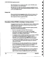
The command 'lit i l it ies /Zpecials LECO Level' will allow you to
enter or verify this at a later time if desired.
The VBT-325 is now ready. to run, and can be operated immediately from the
VT100 emulator that comes with the firmware distribution diskette, or you can
move to your familiar terminal.
Setups lost
Please note that the firmware upgrade procedure will clear all contents of the
non-volatile memory on the VBT-325, causing all stored setups to be lost.
This completes the firmware upgrade procedure.
* * * * *
Procedure if Boot PROM is missing or wrong version
To upgrade firmware from a PC to a VBT-325, there must be a PROM installed
in the 32-pin socket on the board. If a PROM of wrong version is already
installed, this must be replaced.
To install the Boot PROM and to complete the firmware upgrade procedure,
please follow the instructions given below:
• P o w e r down the system in which the VBT-325 is inserted.
• T a k e out the VBT-325 and leave it on a surface with controlled
characteristics with respect to static electricity (ref. "Static Electricity -
Precautions" in the "INSTALLATION" section.)
• I f a piggyback module is installed, this must be removed before the PROM •
can be replaced or inserted, please refer to "Piggyback removal
instructions" in the User's Manual for the piggyback modules (for the
VBAT-PB, this is included in the section VBAT-PB in this manual.)
• I f a PROM is already installed in the 32-pin socket, remove this carefully
with a screwdriver etc. NB: Take care not to damage the components
underneath the PROM!
• I f the jumper in pos. J21, close to the big PLD device, is inserted, then
remove it. (If this jumper is present, the board has been run and booted
from FLASH PROMs only, without any separate Boot PROM.)
• C h e c k that the position of the jumpers J22 and J23 are installed as shown
in figure A2 below.
• I n s e r t the new boot PROM into the 32-pin socket. If the boot PROM is a
28-pin device, leave four vacant pins closer to the pin 1 marking (see
figure A2 below). The pin 1 is marked with a little "notch" in the silk
134
V
B
T
-
3
2
5
User's Manual
V
M
E
T
R
O
Содержание VBAT-PB
Страница 15: ...x i v 1 1 I 1 1 I I i i I I 1 I I 1 I 1 I I ...
Страница 23: ...1VBT 325 Product overview 8 V B T 3 2 5 User s Manual V M E T R O ...
Страница 125: ...8 Trace examples 110 V B T 3 2 5 User s Manual V M E T R O ...
Страница 144: ...9 VBAT PB VME bus anomaly trigger ITP40 I GND VMETRO V B T 3 2 5 User s Manual 1 2 9 ...
Страница 159: ...1 1Jumper settings 144 V B T 3 2 5 User s Manual V M E T R O ...
Страница 181: ...16 Simulator for PC 166 V B T 3 2 5 User s Manual V M E T R O ...


