Refrigerating Specialties Division
3
Disassembly
- Take care when removing Seal Caps 1
and 44 in case some refrigerant may be trapped inside.
Back the Adjusting Stem 6 all the way out to remove any
pressure from Range Spring 13 otherwise damage to
Diaphragm 17 or Pilot Seat 18 may occur. Remove Bonnet
8 by carefully removing Cap Screws 11. Take care not to
damage Diaphragm Follower 15. Remove Adapter 28 by
removing Cap Screws 31. Turn the Manual Opening Stem
33A all the way in until the flats on the stem barely protrude
from the stuffing box nut. Push Piston 30 down against
the spring force. The piston should move freely down and
be returned by the spring force. If the piston is jammed or
sticky, remove Bottom Cap Assembly, which includes
Items 33 through 42, by removing Cap Screws 39 or
unscrewing Bottom Cap, 20mm through 32mm (3/4"
through 1-1/4"). Using a hard wood dowel rod inserted
through the bottom of the valve, tap the piston upward
and out. Thoroughly clean all parts. If jamming has taken
place and the piston and bore are scored, remove all burrs
by polishing the piston, bore and modulating plug with
fine crocus cloth. Inspect the seating area of the
Modulating Plug 33 for damage or erosion. If damaged it
should be replaced. It would be advisable to replace the
entire bottom cap assembly. Inspect all gaskets and “O”
rings for damage and replace where necessary.
Assembly
- When reassembling the valve, all internal
parts should be clean, dry and lightly oiled with refrigerant
oil, except “O” rings. Apply silicone grease to the “O” rings.
Care must be taken especially when the parts are cold
since moisture can condense on parts and cause rapid
rusting. When replacing gaskets, they should be oiled very
lightly with refrigerant oil before assembly. Install bottom
cap assembly first and tighten in place. Carefully replace
the piston; never try to force it in place. Align the Adapter
Gasket 29 carefully with the proper holes in the adapter
and valve body and fasten adapter in place. Before
assembling the bonnet be sure the Adjusting Stem 6 is
turned all the way out. Place Gasket 19, Diaphragm 17
and Gasket 16 in Adapter 28. The raised center of the
diaphragm must be towards the bonnet. Stack Diaphragm
Follower 15, Lower Spring Rest 14, Spring 13 and Upper
Spring Rest 12 on top of diaphragm and carefully lower
bonnet in place and tighten Screws 11 in place. For range
“D” use two diaphragms. Tighten Cap Screws 11 evenly.
The ideal tightening torque is 1.5 Kg-m (11 ft. lbs.). Valve
is now ready to be adjusted for normal operation.
If close coupled strainer is used, it may be cleaned before
putting the valve back in operation. The regulator must be
tested for leaks with refrigerant gas or other appropriate
gas before the system is put into operation.
A4A
After the General Procedure for disassembly, inspect the
Pilot Seat 18 top seating surface for dirt, wear or damage.
Remove seat from valve body and clean, lap on a flat
plate or replace as necessary. Examine the diaphragm
region which contacts the seat surface, look for dirt, heavy
scratches or corrosion. If the diaphragm cannot be easily
wiped clean, it should be replaced. Reassemble the
regulator following the General Procedure.
A4AK
For disassembly and assembly follow the General
Procedure and the procedure for A4A. This regulator has
a sealed wire connection to keep the seal cap from being
removed. This wire must be removed before the regulator
can be disassembled. Please Note: Removal of the seal
voids any Refrigerating Specialties Division factory
responsibility for the regulator pressure set-point.
Adjustment
Install an accurate pressure gauge in the gauge port. Back
the adjusting stem all the way out to stop. This will reduce
the set point to its lowest level and cause the valve to
open wide. Start the system, and when suction pressure
is about the desired pressure, turn the adjusting stem in
until the pressure gauge shows a slight rise in the inlet
pressure. At this point the adjusting stem may be turned
in (clockwise) to raise the pressure further, or backed out
(counterclockwise) to lower it; but the final adjustment
should be made after the system has been operating for
a period of time.
INLET PRESSURE SETTING RANGES
Approx. Pressure Change Factory Set Point
Set Point Ranges
per Turn of
(unless otherwise)
Adjusting Screw
specified)
A:
0 to 10.3 bar
1 .7 bar (25 psi)
2.8 bar (40 psig)
(0 to 150 psig)
V:
500mm hg to 8.3 bar
1 .7 bar (25 psi)
1 . 0 bar (15 psig)
(20in hg to 120 psig)
D:
5.2 to 19.3 bar
3.7 bar (53 psi)
9.7 bar (140 psig)
(75 to 280 psig)
A4AE Inlet Pressure Regulator,
Remote Sensing Connection
This regulator allows control of upstream pressure at a
point remote from the regulator inlet. Gasket 19 has no
hole, thus blocking flow of upstream pressure to under
the diaphragm. The sensing pressure from the desired
control point, upstream of the regulator, is connected to
the gauge port leading to under the diaphragm. Thus the
regulator will control the pressure at this point. The
regulator operation and adjustment is the same as for
A4A.
(continued on page 8)
Содержание VSM 71-701
Страница 1: ...1 VPN 35391S February 2006 Rev 05 Price 60 00...
Страница 2: ...2...
Страница 20: ...20...
Страница 52: ...53 Pre Start Up Check List...
Страница 99: ...99 Recommended Spare Parts List...
Страница 104: ...104 Gate Rotor...
Страница 110: ...110 Main Rotor VSS...
Страница 112: ...112 Main Rotor VSR...
Страница 114: ...114 Slide Valve Cross Shafts and End Plate...
Страница 118: ...118 Capacity Slide Volume Slide Carriage Assembly Slide Valve Carriage Assembly...
Страница 134: ...134 Miscellaneous Frame Components VSS Screw Compressor VSR Mini Screw Compressor...
Страница 138: ...138 C FlangeAdapter Components 630 620 610 640 601 641 630 601 620 610 640 641 642 650 651...
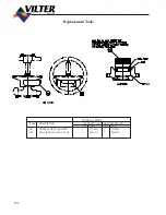
Страница 140: ...140 Replacement Parts Tools...
Страница 144: ...144 GaterotorAssembly...
Страница 148: ...148 Main Rotor Slide Valve Cross Shafts and End Plate Models 71 401 Only Counter clockwise...
Страница 151: ...151 See Next Page for Models 501 701 Main Rotor Slide Valve Cross Shafts and End Plate V S M Parts List...
Страница 152: ...152 Main Rotor Slide Valve Cross Shafts and End Plate Model 501 701 Only Clockwise...
Страница 154: ...154 Volume Ratio Capacity Slide Carriage Assembly Slide Valve Carriage Assembly...
Страница 158: ...158 Miscellaneous Frame Components Model VSM 501 701 Model VSM 71 401...
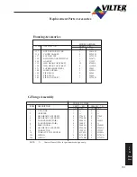
Страница 160: ...160 Replacement Parts Accessories Housing Accessories C Flange Assembly...
Страница 166: ...166 Haight Pumps...
Страница 170: ...3 Refrigerating Specialties Division...
Страница 184: ...C A R T R I D G E H E A T E R S Hi Temp Cartridge heaters are designed for optimum performance above and beyond the norm...
Страница 236: ......
Страница 237: ......
Страница 238: ......
Страница 243: ......
Страница 244: ...168...


