164
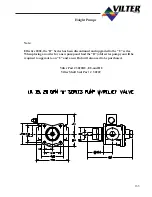
Haight Pumps
10-80 GPM OIL PUMPS
VILTER PART NUMBER
3022UB, EU and HU
HAIGHT MODEL 10-80U Series
PREPARATION OF OIL PUMP
FOR MAINTENANCE
1
Prepare compressor unit for servicing
as outlined in the service section of the manual.
2.
Remove the refrigerant from the unit in
an appropriate manner and equalize to atmospheric
pressure.
3.
Isolate the oil pump in the oil circuit.
4.
Make sure that the electricity is turned
off to the oil pump motor and remove the 4 bolts
and washers from the oil pump mounting face (25
and 26), remove bolts securing the motor to the
unit and slide the oil pump motor from the oil pump.
5.
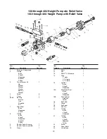
Remove the set screw from the coupling
half and slide the coupling off of the oil pump shaft.
Remove the key (1) from shaft.
6.
Using fine emery paper remove any burrs
from the key way area and the end of the
shaft.
SHAFT SEAL INSPECTION.
REMOVAL AND INSTALLATION.
1.
Prepare the pump for servicing as stated
in the previous paragraph.
2.
Remove the seal housing by unscrewing
the cap (2) using care as the seal in compressed
with a spring, therefore the cap may release towards
the key way as the cap is unscrewed. With the cap
unscrewed, slide it off of the shaft. The seal (21)
will now be visible, but possibly under compres-
sion as the bellows of the
seal may be sticking to the shaft.
Carefully, rotate the shaft and inspect the bellows
of the seal for damage. If it is damaged the seal
must be replaced at this time. If the bellows is in
good shape, then the carbon face and the matting
face of the seal will need to be inspected for crack-
ing or excessive wear. If they are damaged the seal
must be replaced at this time.
3.
Replace cap "o"-ring (3) at this time.
4.
If the shaft seal is to be replaced, remove
the stationary portion of the seat from the
inside of the cap. The stationary portion of the seal
is pressed in finger tight and is held in place by an
"o"-ring.
IMPORTANT
Care must be taken when installing the seal as
not to touch or scratch the polished side or the
carbon portion of the seal
.
5.
Install the new stationary portion of the
seal in the cap with the polished surface faces the
rotating portion of the seal when assembled. Lu-
bricate the "o''-ring of the stationary portion of the
seal with clean compressor oil to facilitate the in-
stallation.
6.
Remove the rotating portion of the seal
from the oil pump shaft Oil the shaft to aid in the
removal of the seal. The bellows may stick to the
shaft, this is a normal, this wilt require a little pres-
sure to start it moving. After the rotating portion
of the seal is removed, inspect the shaft (22) for
damage and replacd if necessary.
7.
Lubricate the shaft with dean com-
pressor oil and push the replacement seal on to the
shaft taking care not to touch the carbon face of the
seal.
8.
Screw the cap back on to the pump hous-
ing and torque 40 to 60 ft.lbs.
9.
Re-install the key and coupling, tighten
the set screw after it is determined that the cou-
plings mate up correctly. Pressurize and leak check
the unit concentrating on areas that repairs were
made.
10.
It is normal for the seal to weep a small
amount of oil on start-up until the bellows takes a
set on the shaft.
Содержание VSM 71-701
Страница 1: ...1 VPN 35391S February 2006 Rev 05 Price 60 00...
Страница 2: ...2...
Страница 20: ...20...
Страница 52: ...53 Pre Start Up Check List...
Страница 99: ...99 Recommended Spare Parts List...
Страница 104: ...104 Gate Rotor...
Страница 110: ...110 Main Rotor VSS...
Страница 112: ...112 Main Rotor VSR...
Страница 114: ...114 Slide Valve Cross Shafts and End Plate...
Страница 118: ...118 Capacity Slide Volume Slide Carriage Assembly Slide Valve Carriage Assembly...
Страница 134: ...134 Miscellaneous Frame Components VSS Screw Compressor VSR Mini Screw Compressor...
Страница 138: ...138 C FlangeAdapter Components 630 620 610 640 601 641 630 601 620 610 640 641 642 650 651...
Страница 140: ...140 Replacement Parts Tools...
Страница 144: ...144 GaterotorAssembly...
Страница 148: ...148 Main Rotor Slide Valve Cross Shafts and End Plate Models 71 401 Only Counter clockwise...
Страница 151: ...151 See Next Page for Models 501 701 Main Rotor Slide Valve Cross Shafts and End Plate V S M Parts List...
Страница 152: ...152 Main Rotor Slide Valve Cross Shafts and End Plate Model 501 701 Only Clockwise...
Страница 154: ...154 Volume Ratio Capacity Slide Carriage Assembly Slide Valve Carriage Assembly...
Страница 158: ...158 Miscellaneous Frame Components Model VSM 501 701 Model VSM 71 401...
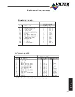
Страница 160: ...160 Replacement Parts Accessories Housing Accessories C Flange Assembly...
Страница 166: ...166 Haight Pumps...
Страница 170: ...3 Refrigerating Specialties Division...
Страница 184: ...C A R T R I D G E H E A T E R S Hi Temp Cartridge heaters are designed for optimum performance above and beyond the norm...
Страница 236: ......
Страница 237: ......
Страница 238: ......
Страница 243: ......
Страница 244: ...168...

