58
Service
0.00
GENERAL COMMENTS
When working on the compressor, care must be
taken to ensure that contaminants (i.e. water from
melting ice, dirt and dust) do not enter the com-
pressor while it is being serviced. It is essential
that all dust, oil or ice that has accumulated on
the outside of the compressor be removed before
servicing the compressor.
When servicing the compressor, all gaskets, O-
rings, roll pins and lock washers must be replaced
when reassembling the compressor.
It is important that if the refrigerant requires the
use of a Polyolester (POE) refrigeration oil, that
all oil is removed from the compressor unit after
the unit has been opened to the atmosphere for
servicing. POE refrigeration oils are highly
hydroscopic and will absorb large quantities of
moisture in a short time, when exposed to the
atmosphere during servicing. Once the moisture
is absorbed into the oil it is nearly impossible to
remove the moisture from the oil.
0.01
PREPARATION OF UNIT FOR
SERVICING
A) On Cool Compression units, while the unit is
running, close the main liquid ammonia line
(located before the thermostatic expansion
valve) and wait for the unit to stop by itself.
This operation will remove all the liquid am-
monia from the separator. The compressor
will stop when the superheat at discharge
reaches 25°F.
B)
Shut down the unit, open the electrical dis-
connect switch and pull the fuses for the com-
pressor motor to prevent the unit from start-
ing. Put a lock on the disconnect switch and
tag the switch to indicate that maintenance
is being performed.
C)
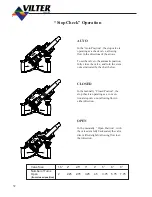
Isolate the unit by manually closing the dis-
charge Stop/Check valve. If the unit is
equipped with a V-PLUS
®
or liquid injection
cooling system, close the liquid supply valves
and open all solenoid valves to prevent liq-
uid refrigerant from being trapped between
the stop valves and solenoid valves. Allow
the unit to equalize to suction pressure be-
fore closing the Suction Bypass or Stop/
Check valve. After the unit has equalized to
suction pressure and suction valve closed,
use an acceptable means to depressurize the
unit that complies with all Local, State and
Federal Ordinances.
D) Remove drain plugs from the bottom
ofcompressor housing and the discharge
manifold On units equipped with Suction Oil
Injection (SOI) manually open the SOI sole-
noid valve below the compressor. Drain the
oil into appropriate containers.
0.02
REMOVAL OF COMPRESSOR
FROM THE UNIT
After Preparing the unit for service the following
steps should be followed when removing the com-
pressor from the unit:
A) Disconnect the motor drive coupling from the
compressor input shaft.
B)
Disconnect all gas and oil piping which is
attached to the compressor. When removing
the suction strainer on VSS/VSM units or the
suction line from VSR units, the suction line
should be supported to prevent it from sag-
ging.
C)
Replace oil drain in compressor housing and
discharge manifold after oil has stopped
draining.
All Oil must be removed from unit.
D) Remove all electrical connections to the com-
pressor.
Содержание VSM 71-701
Страница 1: ...1 VPN 35391S February 2006 Rev 05 Price 60 00...
Страница 2: ...2...
Страница 20: ...20...
Страница 52: ...53 Pre Start Up Check List...
Страница 99: ...99 Recommended Spare Parts List...
Страница 104: ...104 Gate Rotor...
Страница 110: ...110 Main Rotor VSS...
Страница 112: ...112 Main Rotor VSR...
Страница 114: ...114 Slide Valve Cross Shafts and End Plate...
Страница 118: ...118 Capacity Slide Volume Slide Carriage Assembly Slide Valve Carriage Assembly...
Страница 134: ...134 Miscellaneous Frame Components VSS Screw Compressor VSR Mini Screw Compressor...
Страница 138: ...138 C FlangeAdapter Components 630 620 610 640 601 641 630 601 620 610 640 641 642 650 651...
Страница 140: ...140 Replacement Parts Tools...
Страница 144: ...144 GaterotorAssembly...
Страница 148: ...148 Main Rotor Slide Valve Cross Shafts and End Plate Models 71 401 Only Counter clockwise...
Страница 151: ...151 See Next Page for Models 501 701 Main Rotor Slide Valve Cross Shafts and End Plate V S M Parts List...
Страница 152: ...152 Main Rotor Slide Valve Cross Shafts and End Plate Model 501 701 Only Clockwise...
Страница 154: ...154 Volume Ratio Capacity Slide Carriage Assembly Slide Valve Carriage Assembly...
Страница 158: ...158 Miscellaneous Frame Components Model VSM 501 701 Model VSM 71 401...
Страница 160: ...160 Replacement Parts Accessories Housing Accessories C Flange Assembly...
Страница 166: ...166 Haight Pumps...
Страница 170: ...3 Refrigerating Specialties Division...
Страница 184: ...C A R T R I D G E H E A T E R S Hi Temp Cartridge heaters are designed for optimum performance above and beyond the norm...
Страница 236: ......
Страница 237: ......
Страница 238: ......
Страница 243: ......
Страница 244: ...168...


