89
Service
B)
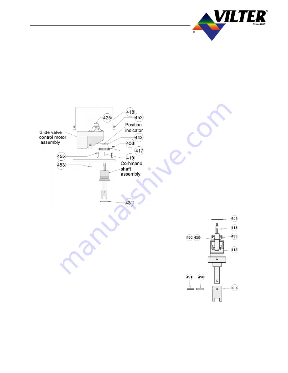
Remove the hex head cap screws (452) from
the cover (418) for the slide valve control
motor, and remove cover. Mark and discon-
nect the wires to the slide valve control motor
and potentiometer (425). Remove the two hex
bolts (453) under the mounting plate (415) that
hold the motor bracket (405) in place. The
motor can now be removed.
C)
Removes the four socket head cap screws
(455) securing the motor plate and command
shaft assembly. The motor plate and com-
mand shaft assembly can now be removed
from the discharge manifold.
D) Repeat the above steps to remove the oppo-
site slide valve control motor and command
shaft assembly.
4.32
INSTALLATION OF RETROFIT
CONTROL ASSEMBLY
A) Install the new command shaft assembly with
a new O-ring on the manifold. Make sure the
command shaft coupling is engaged in the
cross shaft gear. Rotate the bearing housing
so the vent holes points down, to prevent
water and dust from entering the vent.
B)
Install the new motor plate (415) and the four
socket head cap screws (457), and Nord-
Lock
®
washers (477) securing it. Tighten the
bolts to the recommended torque value.
C)
Install the drive key (427) in the command
shaft keyway.
D) Install the new style optical gear motor as
outlined in section 4.02 Optical Slide Valve
Actuator Installation.
E)
Refer to the appropriate Microprocessor op-
erating manual for the procedure to recalibrate
the actuator. The unit can now be evacuated
and leak checked as outlined in section 0.03.
4.33
COMMAND SHAFT BEARING
AND O-RING SEAL REPLACEMENT
FOR RETROFIT CONTROL AS-
SEMBLIES
A) Remove command shaft assembly as outlined
in section 4.05.
B)
With a suitable pin punch, drive out roll pins
(490) and (491). Remove coupling (414) from
the command shaft and dress out any burrs
around the roll pin hole on the command shaft.
C)
Remove snap ring retainer (451) from com-
mand shaft housing (412). Push the com-
mand shaft assembly out of the housing.
Содержание VSM 71-701
Страница 1: ...1 VPN 35391S February 2006 Rev 05 Price 60 00...
Страница 2: ...2...
Страница 20: ...20...
Страница 52: ...53 Pre Start Up Check List...
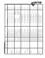
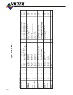
Страница 99: ...99 Recommended Spare Parts List...
Страница 104: ...104 Gate Rotor...
Страница 110: ...110 Main Rotor VSS...
Страница 112: ...112 Main Rotor VSR...
Страница 114: ...114 Slide Valve Cross Shafts and End Plate...
Страница 118: ...118 Capacity Slide Volume Slide Carriage Assembly Slide Valve Carriage Assembly...
Страница 134: ...134 Miscellaneous Frame Components VSS Screw Compressor VSR Mini Screw Compressor...
Страница 138: ...138 C FlangeAdapter Components 630 620 610 640 601 641 630 601 620 610 640 641 642 650 651...
Страница 140: ...140 Replacement Parts Tools...
Страница 144: ...144 GaterotorAssembly...
Страница 148: ...148 Main Rotor Slide Valve Cross Shafts and End Plate Models 71 401 Only Counter clockwise...
Страница 151: ...151 See Next Page for Models 501 701 Main Rotor Slide Valve Cross Shafts and End Plate V S M Parts List...
Страница 152: ...152 Main Rotor Slide Valve Cross Shafts and End Plate Model 501 701 Only Clockwise...
Страница 154: ...154 Volume Ratio Capacity Slide Carriage Assembly Slide Valve Carriage Assembly...
Страница 158: ...158 Miscellaneous Frame Components Model VSM 501 701 Model VSM 71 401...
Страница 160: ...160 Replacement Parts Accessories Housing Accessories C Flange Assembly...
Страница 166: ...166 Haight Pumps...
Страница 170: ...3 Refrigerating Specialties Division...
Страница 184: ...C A R T R I D G E H E A T E R S Hi Temp Cartridge heaters are designed for optimum performance above and beyond the norm...
Страница 236: ......
Страница 237: ......
Страница 238: ......
Страница 243: ......
Страница 244: ...168...


