ECLECTRICAL INSTALLATION
User Manual 10H52246UM60 - Rev. 1 - 01/2017
31
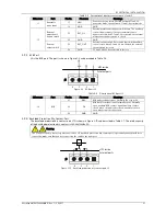
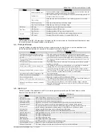
Table 3-5
Description of input dry contact ports J1 and J5
Silkscreen
Port
Pin No.
Pin name
Meanings
J1
Generator
mode input
1.1 GEN
Generator is connected. Shorted between 1.1 and 1.2:
generator mode; open between 1.1 and 1.2: normal mode
1.2 GND
GND
J5
External
maintenance
bypass switch
5.1 EXT_Q3
External maintenance bypass switch state. The auxiliary
contact requirement of the external maintenance
bypass switch: when 5.1 and 5.2 are shorted, the external
maintenance bypass switch is closed
5.2 GND
GND
External
output switch
5.3 EXT_OUT
External output switch. External output switch auxiliary
contact state: when 5.3 and 5.4 are shorted, the external
output switch is closed.
5.4
GND
5.3 and 5.4 have been shorted in factory
3.2.3
BCB Port
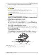
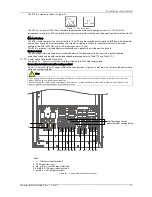
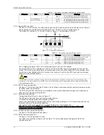
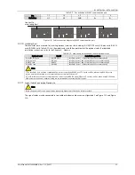
J2 is the BCB port. The port is shown in Figure 3-9 and described in Table 3-6.
1
2
3
4
J4
GN
D
UPS inside
External ports
J2
Figure 3-9
BCB port J2
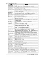
Table 3-6
Description of BCB port J2
Silkscreen
Port
Pin No.
Pin name
Meanings
J2 BCB
2.1
DRV
BCB undervoltage release. Normally 12V, trip at 0V
2.2 FB
BCB backfeed signal input (normally open). Normally
open auxiliary BCB contact signal: Auxiliary contact
closed when circuit breaker closed; auxiliary contact
open when circuit breaker open.
2.3 GND
GND
3.2.4
Backfeed Protection Dry Contact Port
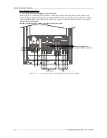
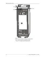
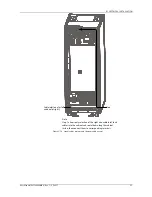
The backfeed protection dry contact port J13 is shown in Figure 3-10 and described in Table 3-7. The rated capacity
of the backfeed protection dry contact is 240Vac/24Vdc, 5A.
Warning
The voltage of the dry contact signal connected to J13 backfeed protection dry contact port is potentially hazardous. Before
connection, make sure that you are connecting the cable to the right port.
J5
UPS
内部
外部接口
1
2
3
4
J5
UPS inside
External ports
1
2
3
4
J5
UPS inside
External ports
J3
Figure 3-10
Backfeed protection dry contact port J3

