OPTION
User Manual 10H52246UM60 - Rev. 1 - 01/2017
75
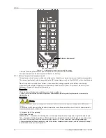
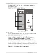
Figure 8-12
Connection between UF-RS485 card and battery temperature sensor
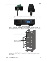
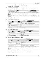
3. As illustrated in Figure 8-13, set the temperature sensor DIP switch 5 to 'ON', so that the bottom left corner of the
temperature sensor display LCD screen indicates 01 (or 02). If two temperature sensors are used together, their DIP
switch settings must not be the same.
Figure 8-13
Temperature sensor DIP switch
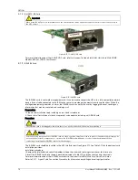
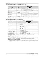
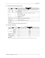
4. Remove the right side panel of the cabinet, position the battery temperature sensor at the rear of battery tray 1,
and then insert the UF-RS485 card into the Intellislot port 1. Refer to Figure 8-14 for more information on installing
and connecting the battery temperature sensor.
Installation position of
Route cable to Intellislot 1 port
battery temperature sensor
Figure 8-14
Installing and connecting the battery temperature sensor
5. Route the cables as indicated in Figure 8-14. Note that the cables should be routed separately from the power
cables, to avoid EMI.


