PARALLEL SYSTEM AND LBS SYSTEM
64
User Manual 10H52246UM60 - Rev. 1 - 01/2017
7.3.4
Procedures for Reintegrating an Isolated UPS Module into a Parallel System
Important
These procedures may only be carried out Vertiv service personnel or under their guidance.
The following procedures are used to reintegrate a UPS module that has been previously isolated from the parallel
system:
1. If the UPS is connected to an external battery, simply close the external battery distribution switch or connect the
three terminals 'BAT+', 'BAT-' and 'BAT N' (see Figure 5-3 for details). Then close the rectifier input switch Q1 and
neutral line switch Q6.
At this point, the system power is on, and the startup screen appears. Refer to 4.2.1
Start Screen
.
2. Close the bypass input switch Q2.
Confirm that the LCD indicates that the bypass input supply is normal; if not, check whether the switch Q2 is closed.
At this point the rectifier starts up and the alarm indicator (red) is illuminated. About 30 seconds later, the alarm
indicator (red) starts flashing (if the UPS internal or external battery is not connected) or is extinguished (if the UPS
internal and/or external batteries are connected).
3. Close the output switch Q5, and press the ON key for two seconds.
The inverter starts up, and the inverter indicator (green) starts flashing. Once the inverter is running normally, the
UPS transfers from the bypass to inverter, and the inverter indicator (green) is illuminated (no longer flashing).
At this point, the UPS will be fully reintegrated into the parallel system, and start supplying power to the load.
7.3.5
Procedures for Shutting Down a UPS Completely in a Parallel System
To shut down and de-energize a UPS completely, proceed as follows. Upon completion of this procedure, all the UPS
power switches, isolating switches and circuit breakers must be open, so that the UPS is fully de-energized and no
longer supplies power to the load.
Caution
The following procedures will interrupt all power supplies to the load so that it switches off.
1. Pressing the EPO button on each shuts down the corresponding rectifier, inverter, static switch and battery
charger.
2. If the UPS has internal battery, use the special tool to open the battery compartment, then disconnect the three
terminals 'BAT+', 'BAT-' and 'BAT N' (see Figure 5-3 for details). If the UPS has external battery, disconnect the
corresponding external battery switch. All UPS modules should be disconnected from the batteries.
3. Open the rectifier input switch Q1 and bypass input switch Q2 on each UPS. At this point, all the internal UPS
power supplies are disconnected and the LCD does not display any more.
4. Open the output switch Q5 on each UPS.
Warning
1. Position a label at the AC input distribution (normally located at a distance from the UPS) alerting personnel that
maintenance is being carried out on the UPS.
2. Wait 10 minutes for the internal DC bus capacitors to discharge completely. At this point the UPS is completely shut down.
Warning: hazardous battery voltage
Hazardous voltages are still present on the battery terminals, even after the UPS has been completely shut down.
7.3.6
Procedures For Complete UPS Shutdown While Maintaining Power To Load
The following procedures can be used to shut down the UPS completely without interrupting the power supply to
the load. Refer to the procedures in para. 7.3.2
Maintenance Bypass Procedures
.
7.4
LBS System
7.4.1
Cabinet Installation
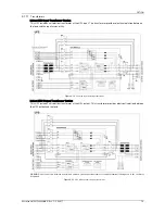
An LBS system consists of two independent UPS systems, each consisting of one or more UPS modules connected
in parallel, as shown in Figure 7-4 and Figure 7-5. LBS systems provide high reliability and are suitable for use with
multiple input loads. In the case of single-input loads, an STS can be installed to feed power to the load.
The system uses the LBS cables to ensure the outputs of the two independent (or parallel) UPS systems remain
synchronized. One system is designated as the master, the other is designated as the slave. The operating modes of
the parallel system care master and/or slave operation in normal or bypass mode.
Place the UPS modules side by side and interconnect the UPS modules as described below.


