OPTION
68
User Manual 10H52246UM60 - Rev. 1 - 01/2017
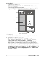
A
Base plate
Cable connection terminal
Sems screw
A
B
C
Inductors A/B/C
A Amplified view
Figure 8-2
Position of bypass load sharing inductors
There are 12 installation holes on the base plate of the UPS cabinet for fixing the three inductors, four installation
holes for each inductor. Place the three inductors in the installation positions shown in Figure 8-2, and secure them
to the base plate of the UPS cabinet using the M5 × 12 SEMS screws (12 pcs).
4. Connection of bypass load sharing inductors.
a) Remove the fixing screws on three cables W01, W02 and W03.
b) Refer to Figure 8-3, connect one end of W31 ~ W36 to inductor A, Inductor B, and Inductor C, respectively. Use
the M6 × 16 SEMS screws, M6 flat washers and nuts to secure them to the terminals. The torque value is 4.8N.m.
bA
bB
bC
1
2
1
2
1
2
W01 Q2-1
W04 P-A
W02 Q2-3
W05 P-B
W03 Q2-5
W06 P-C
P
Figure 8-3
Inductor connections (1)
c) Connect the other end of cables W31 ~ W33 to the corresponding terminals on top of bypass Input switch Q2, and
use the M6 × 16 SEMS screws to secure them to the terminals. The torque value is 4.8N.m. See Figure 8-4.


