184
Firmware Version 5.4
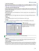
• PWM Standby
This is a user-defined setting that determines the percent duty cycle the system uses when the booms are
all off. The setting must be greater than the Zero Flow Offset.
Note: The current PWM Duty Cycle can be viewed at the Liquid Diagnostics screen. For more information,
see
“Liquid Application Diagnostics” on page 193
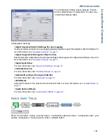
Control Valve Settings - Servo, Calibrated Reflow and Ramsey Valve
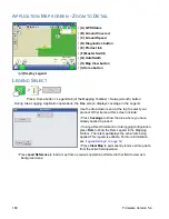
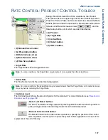
• Valve Response 1
Determines the speed of the servo valve when
product control error exceeds the Response
Threshold setting. The default for this setting is
100%. Decreasing the value will cause the servo
valve to run slower. Valve Response 1
represents the fast speed of the servo valve.
• Valve Response 2
Determines the speed of the servo valve when
product control error is less than the Response
Threshold setting. The default for this setting is
24%. Decreasing the value will cause the servo
valve to run slower. Valve Response 2
represents the slow speed of the servo valve.
• Response Threshold
Determines where the control channel switches between using Valve Response 1 and Valve Response 2
speed settings. The default setting is 3. Leaving all other valve control settings at the default value and
making a small adjustment to this setting is usually all that is required to fine-tune system performance.
- Decreasing this value will have the overall effect of speeding up servo valve response.
- Increasing this value will have the overall effect of slowing servo valve response.
Calibrate Pressure
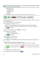
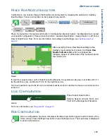
Press: Home button > Setup (wrench) button > Configuration (tractor) button > Configuration tab > select
your specific configuration > Setup (wrench) button > Calibrate Pressure button
Choose Main, Agitation or Aux from drop-down box. Press
to continue.
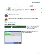
Press
to enter pressure value as a set point or press Reset to Default button. Press
to
continue.
Press
to enter voltage/pressure ratio. Press
to continue.
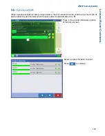
Press
to finish process.
3 gal/min
Control Valve Settings
Control Valve:
Inline Servo
Valve
Response 1
Valve
Response 2
Response Threshold
100
24
Allowable
Error
2 %
Configuration
Select Your Specific
Configuration
Calibrate Pressure
Содержание ag leader
Страница 1: ...Operators Manual Firmware Version 5 4 Ag Leader PN 4002722 Rev G ...
Страница 2: ...Firmware Version 5 4 ...
Страница 20: ...6 Firmware Version 5 4 ...
Страница 38: ...24 Firmware Version 5 4 For more information see Legend Settings on page 52 ...
Страница 55: ...41 SETUP M ANAGEMENT S ETUP Remove button Press to remove a business ...
Страница 56: ...42 Firmware Version 5 4 ...
Страница 78: ...64 Firmware Version 5 4 ...
Страница 82: ...68 Firmware Version 5 4 Press to Export All Log files Export All Log Files ...
Страница 84: ...70 Firmware Version 5 4 ...
Страница 94: ...80 Firmware Version 5 4 ...
Страница 108: ...94 Firmware Version 5 4 ...
Страница 140: ...126 Firmware Version 5 4 ...
Страница 154: ...140 Firmware Version 5 4 ...
Страница 158: ...144 Firmware Version 5 4 ...
Страница 162: ...148 Firmware Version 5 4 ...
Страница 222: ...208 Firmware Version 5 4 ...
Страница 244: ...230 Firmware Version 5 4 ...
Страница 260: ...246 Firmware Version 5 4 ...
Страница 289: ...275 HARVEST H ARVEST M ONITORING M APPING Motor Current Measure of Elevator Mount Unit EMU current shown in amps ...
Страница 290: ...276 Firmware Version 5 4 ...
Страница 304: ...290 Firmware Version 5 4 ...

