


102
VTK-VS-BA-015e-A | User Manual MDS 3200+ Series
|
Maintenance
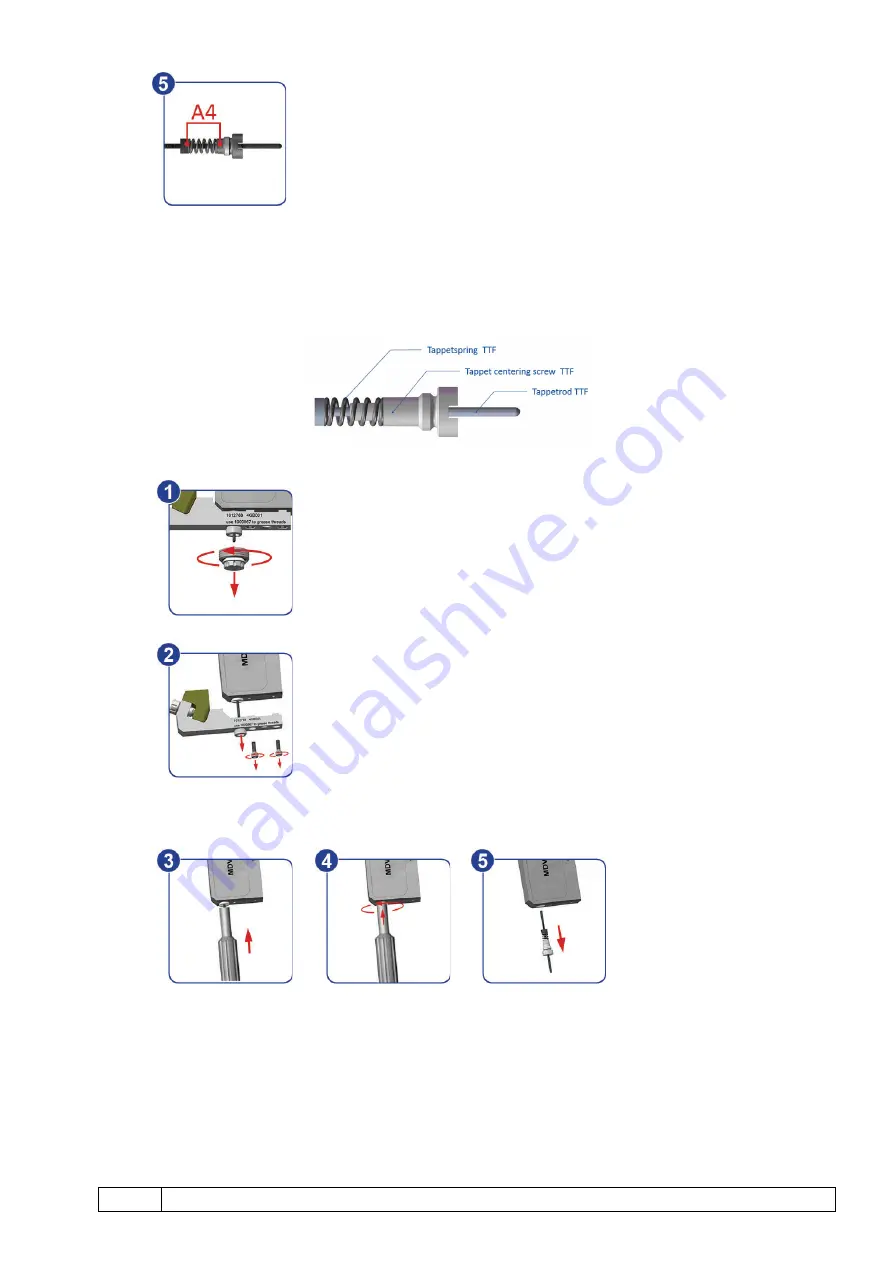
Step 5:
The complete spring
(A4)
must be greased with a small amount of grease.
The tappet can be inserted, and the dispensing process may be continued after the adjust.
9.3.2
TTF- and CTF-Tappet
9.3.2.1
Demounting
Step 1:
Carefully remove the nozzle unit from the fluid box.
(1)
Step 2:
Both M2,5 hexagon screws of the fluid box must be loosened and un-
screwed. Slowly slide away the fluid box from the tappet. The fluid box
must not be jammed, otherwise the tappet may break off!
(2)
Step 3:
To unscrew the tappet itself, proceed as follows:
−
Tool MDT 310 features a receptacle bore for the tappet. This bore has to be
pushed carefully over the tappet, until the studs of the tool latch in the corre-
sponding recess of the tappet centering screw
(3).
−
In order to disengage the tappet, rotate the tool counter-clockwise, with a
slight constant pressure
(4).
−
Separate the tool from the tappet. The tappet can now be removed through
the case bore of the valve
(5).
Содержание MDS 3200+ Series
Страница 1: ......
Страница 117: ...VTK VS BA 015e A User Manual MDS 3200 Series Attachments 117 13 ATTACHMENTS 13 1 EC Declaration of Conformity...
Страница 118: ...118 VTK VS BA 015e A User Manual MDS 3200 Series Attachments 13 2 Dimensional Drawing MDC 3200...
Страница 119: ...VTK VS BA 015e A User Manual MDS 3200 Series Attachments 119 13 3 Dimensional Drawing MDV 3200A...
Страница 120: ...120 VTK VS BA 015e A User Manual MDS 3200 Series Attachments 13 4 F Dimensional Drawings MDV 3200F...
Страница 121: ...VTK VS BA 015e A User Manual MDS 3200 Series Attachments 121...
Страница 122: ...122 VTK VS BA 015e A User Manual MDS 3200 Series Attachments 13 5 Connection Diagram PLC Interface...