VEMAG ROBOT HP7C Скачать руководство пользователя страница 54

6. Cleaning

ROBOT HP7C / HP10C / HP15C / HP17C

6-10

© VEMAG 2004

6.3 Cleaning the machine

Clean the machine housing, the hopper, the feed screw, the linking gear
(optional) and all the parts which have been removed thoroughly with hot
water and a brush and then dry them. The machine is suitable for cleaning
with low-pressure cleaning equipment (max. 25 bar).

Warning!

Never aim the jet of water directly at the double screw drive, the sealing
elements and the machine control panel when using low-pressure
cleaning equipment and keep the nozzle at the distance from the surface
of the machine specified for the cleaning equipment.

In addition to the instructions in the cleaning schedule, generally-
applicable and product-specific hygiene regulations should be followed.

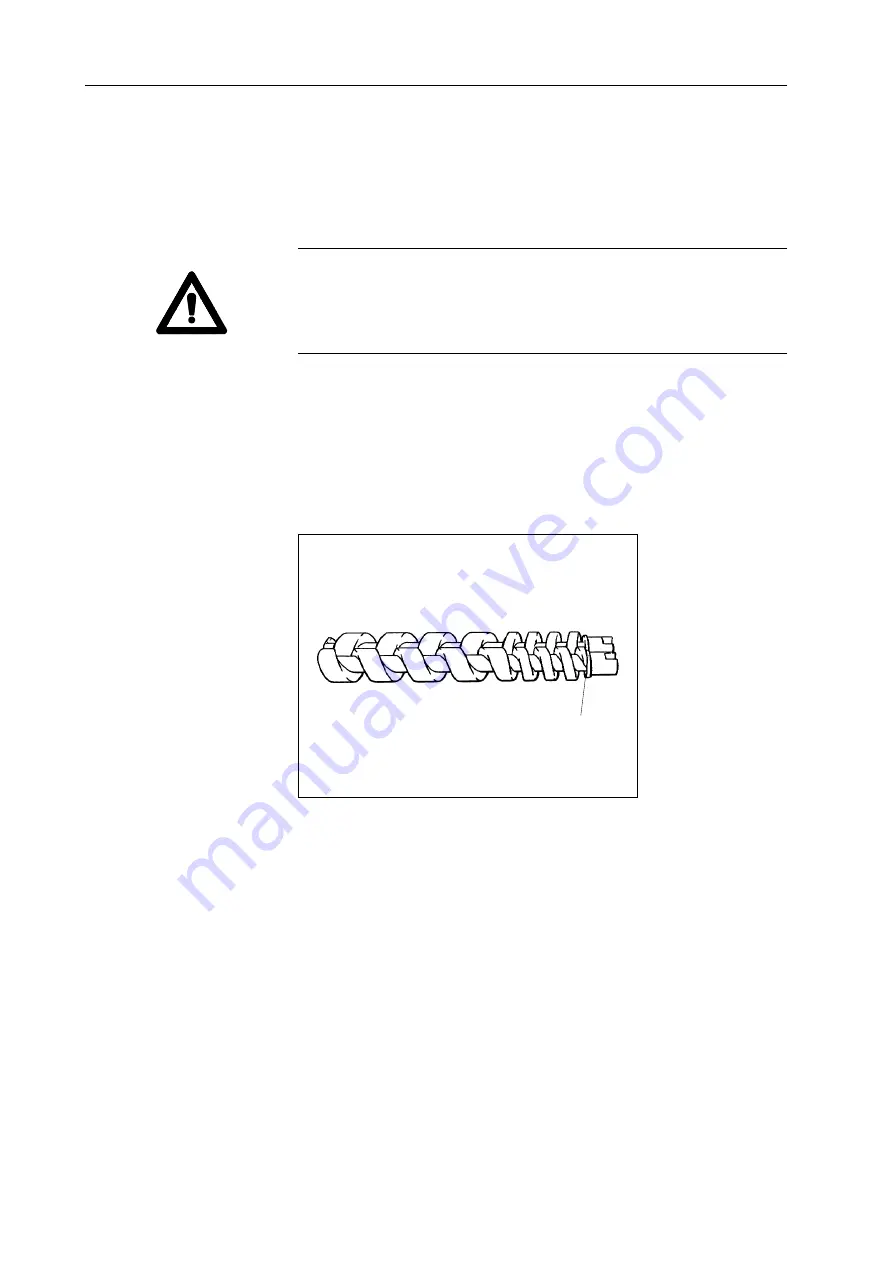
When cleaning the double screws, pay particular attention to the joints
between the screw and the coupling claw (1).

1

1

Joint

Fig. 6-16
Double screws

Содержание ROBOT HP7C

Страница 1: ...Vacuum filler ROBOT HP7C from 146 0132 ROBOT HP10C from 142 1543 ROBOT HP15C from 143 1549 ROBOT HP17C from 147 1552 Operating instructions...

Страница 2: ...will be held liable for the payment of damages All rights reserved in the event of the grant of a patent utility model or ornamental design registration We reserve the right to make technical modifica...

Страница 3: ...2 8 Step 2 7 2 2 9 Adjustable feet 2 7 2 2 10 Lifting tipping device optional 2 7 3 Installation and commissioning 3 1 3 1 Transporting the machine 3 1 3 2 Setting up the machine 3 3 3 3 Electrical co...

Страница 4: ...Maintenance 7 1 7 1 General information 7 1 7 2 Grease gun 7 2 7 3 First time maintenance work 7 2 7 4 Maintenance schedule 7 3 7 5 Daily maintenance 7 4 7 5 1 Feed unit seals lubrication 7 4 7 6 Wee...

Страница 5: ...3 ROBOT HP7C HP10C HP15C HP17C dimensional drawings 9 3 9 4 Vacuum system 9 4 9 5 Hydraulics plan 9 5 9 6 Electrical control panel 9 7 9 7 Power electronics 9 8 9 8 Lubricants 9 9 9 8 1 Double screw...

Страница 6: ...Index iv VEMAG 2004 ROBOT HP7C HP10C HP15C HP17C...

Страница 7: ...parate operating instructions Information on operating the portioning computer can be found in the appropriate user guide If you have any questions which cannot be answered by this manual please conta...

Страница 8: ...0 Foreword 0 2 VEMAG 2004 ROBOT HP7C HP10C HP15C HP17C...

Страница 9: ...etween 4 C and 50 C The vacuum filler requires ambient temperatures between 0 5 C and 25 C The vacuum filler is designed for one operator The operator must have been trained on site by VEMAG specialis...

Страница 10: ...warning symbol refers to important instructions which must be followed to prevent faulty operation which could pose a threat to human life or lead to injury Warning This warning symbol refers to impo...

Страница 11: ...enance department or VEMAG Customer Service informed The machine may not be operated without the housing cover Route mains cables and data cables e g remote control cable so as to avoid tripping hazar...

Страница 12: ...in proper condition Leaking oil indicates leaks which must be eliminated immediately In this case inform your in house maintenance department or VEMAG Customer Service immediately Check that the safet...

Страница 13: ...tenance purposes use only the step provided Under no circumstances use a ladder or other aid to get at the hopper of the machine The hopper is fitted with cushioning as a partial counterweight to prev...

Страница 14: ...the outlet The same volume is conveyed with each rotation of the double screws air being withdrawn from the product by the vacuum system The double screws feed until completely empty The speed of the...

Страница 15: ...urnals 2 and swivelled in front of the outlet It is locked in position at the outlet with the locking nut 3 like the filling horn holder The linking horn 4 is attached to the linking gear with the aid...

Страница 16: ...be connected to the power supply of the machine via equipment socket 2 Instead of blind covers 3 further sockets can be provided for supplementary equipment like coextrusion systems optional for examp...

Страница 17: ...s key switches on the drive of the machine OFF key This key switches off the drive of the machine UP key optional This key raises the trolley hoist of the lifting tipping device optional In the top en...

Страница 18: ...n until the final position is reached Danger When lowering the lifting tipping device ensure that there is no one in this area Do not deposit any objects in this area Vacuum display The vacuum set by...

Страница 19: ...p is fitted with a safety device which switches off the filler as soon as the step is folded out Danger There is a risk of crushing when folding the step in and out Proceed with extreme caution when f...

Страница 20: ...2 Description ROBOT HP7C HP10C HP15C HP17C 2 8 VEMAG 2004...

Страница 21: ...pacity of at least 1 500 kg If at all possible move the fork lift lifting truck under the machine from the outlet side Danger Never tilt the machine when transporting it and when setting it up always...

Страница 22: ...recisely centrally between the feet Warning Place planks 2 between the fork and the machine to prevent the machine slipping during transportation You must ensure that the fork and the planks are pushe...

Страница 23: ...drain off after cleaning The feet 1 can be adjusted using universal spanner 2 If necessary the adjustable feet must be used to compensate for any unevenness in the floor until the machine is absolutel...

Страница 24: ...cal connection may be made only by authorised specialist staff or specialist companies Inside the machine housing connect the machine to the main switch 1 of the machine using four core cable with 3 x...

Страница 25: ...cuum pot Take hold of the float valve on valve body 1 and pull it horizontally off the vacuum line Warning Do not take hold of the float valve at the bottom at the screen to avoid tilting when pulling...

Страница 26: ...ight or level the machine in the horizontal plane the stop parts on the lifting tipping device will have to be reset to obtain the correct height for the trolley Adjust the lifting tipping device as f...

Страница 27: ...ng 3 with the face spanner 4 Use the setting ring 5 to set the desired angle of rotation One turn of the setting ring adjusts the angle of rotation by 2 7 This corresponds to an adjustment in the heig...

Страница 28: ...the guard ring Attach the switch again Lightly grease the contact surfaces of the seals of the drive hood and put the hood back on Then tighten up the mounting bolts again The trolley hoist 1 must be...

Страница 29: ...y locked and is holding the trolley securely in the trolley hoist Then lock the stop screw with the guard nut again If the trolley hoist 1 is correctly level pull the stop bar 2 out far enough for the...

Страница 30: ...3 Installation and commissioning ROBOT HP7C HP10C HP15C HP17C 3 10 VEMAG 2004...

Страница 31: ...ing and the double screws To prevent injury proceed extremely carefully when fitting and dismantling these parts The machine is fitted with an all in one or a two part double screw housing All in one...

Страница 32: ...air bubbles in the product the air relief bores of the double screw housing should be adjusted to suit the product using the setting screws 1 The air relief bores are closed when the screw slots are h...

Страница 33: ...2 into the correct position in relation to the coupling pins in the feed cylinder by turning the double screws in opposite directions Push double screws 1 into double screw housing 2 up to the stop Th...

Страница 34: ...he handle should now be approximately vertical Select a filling horn with the largest possible diameter related to the size of the casing Use the filling horn nut 2 on the filling horn holder 3 to att...

Страница 35: ...gear 1 to the outlet side of the machine with the aid of the two bearing journals 2 Adjust locking nut 1 so that the handle is between the 10 and 11 o clock position and swing linking gear 2 in front...

Страница 36: ...e diameter and shortest possible length related to the size of the casing Fit lip seal 1 in linking horn 2 so that the lug of the lip seal is pointing forwards Grease the seal of the linking horn befo...

Страница 37: ...ing nut 3 using universal spanner 4 Hold the linking head steady with the second universal spanner as you do so Warning The linking head has a left hand thread To tighten turn anti clockwise To loosen...

Страница 38: ...quid product check whether the blind plug is located in the double screw housing If the blind plug is not present the vacuum pump may be destroyed If the vacuum pump takes in product or water as a con...

Страница 39: ...the hopper The scraper must be used when processing raw sausage Danger There is a risk of crushing when fitting and removing the scraper To prevent injury proceed extremely carefully when fitting and...

Страница 40: ...or Undo the hexagonal nut 1 using the universal spanner 2 Adjust the knee lever to the desired height H and angle W Tighten up the hexagonal nut again Move the knee lever plate 3 along the lever shaft...

Страница 41: ...ontinue with the machine In this case inform VEMAG Customer Service immediately Pull on a casing suitable for the product to be filled Push the trolley containing product into the trolley hoist of the...

Страница 42: ...5 Operation ROBOT HP7C HP10C HP15C HP17C 5 2 VEMAG 2004 Unlock the locking lever 1 with your foot and pull the trolley out of the trolley hoist 1 Locking lever Fig 5 1 Trolley 1...

Страница 43: ...ss and check the seals of the double screw drive if vacuum level falls uncontrollably during production Sections 6 and 7 At the start allow the machine to run at a slow speed max 20 until product esca...

Страница 44: ...lley hoist of the lifting tipping device and dismantle the right hand machine cover Switch on the provisional drive switch on the rear of the electrical control panel rocker switch Re fit the right ha...

Страница 45: ...ces optional from the mains and remove the devices Attachment operating instructions Danger The linking gear can heat up at extremely high speeds risk of burns To prevent injury proceed extremely care...

Страница 46: ...6 2 3 Linking gear optional Undo locking nut 1 with the handle anticlockwise until the bayonet lugs 2 come free Swing linking gear 3 to the side Remove filler cone 4 from the linking gear if present...

Страница 47: ...and 6 2 5 Double screw housing Pull the all in one double screw housing two parts of the housing of the two part double screw housing right out of the feed cylinder by hand holding the housing steady...

Страница 48: ...catch in the inlet bore 1 and pull the extraction device 2 out of the double screw housing 3 Warning Proceed carefully when removing the extraction device and be sure to hold the double screw housing...

Страница 49: ...he housing steady with the other hand Then check the rear seal in the feed cylinder for traces of oil Warning You must check the seals of the double screw drive for traces of oil before cleaning If tr...

Страница 50: ...the hopper firmly by flange 2 as you do so Remove the scraper in the hopper if present Push back the three sliding sleeves 3 in the hopper flange holding the feed screw 4 steady with the other hand Ca...

Страница 51: ...he hopper insert 2 Use the appropriate tool at the cleaning plug 3 to do this 6 2 7 Scraper Pull scraper 1 off retaining bolt 2 of the feed screw 1 Sealing ring 2 Hopper insert 3 Cleaning plug Fig 6 1...

Страница 52: ...the valve body 1 and pull it off the intake pipe of the vacuum line in a horizontal direction Warning Do not take hold of the float valve at the bottom on the screen when pulling it off to avoid it ti...

Страница 53: ...6 9 VEMAG 2004 Warning Before cleaning you must plug the cleaning plug onto the intake pipe of the vacuum line to protect the vacuum pump The cleaning plug 1 is located on the front of the machine 1...

Страница 54: ...ng Never aim the jet of water directly at the double screw drive the sealing elements and the machine control panel when using low pressure cleaning equipment and keep the nozzle at the distance from...

Страница 55: ...ructions water jet max 25 bar spray Notes Begin as soon as production finishes Clean small parts at the same time Carry out daily clean small parts at the same time Frequency as required Whole machine...

Страница 56: ...gs without greasing them Section 6 2 6 Lubricate the sealing rings and the sliding ring in the hopper flange by hand before the feed screw is fitted Use a grease for this which has been approved for c...

Страница 57: ...for the feed unit drive to be lubricated The relevant cover of the machine housing has to be removed to allow internal components of the drive system to be serviced Undo the appropriate assembly screw...

Страница 58: ...gun back on and push the piston rod back in pressing down the small retaining lug 4 If no grease emerges after a number of pump strokes vent the grease gun by pressing the relief knob 5 whilst pumping...

Страница 59: ...should also be performed The jobs listed in the maintenance schedule are described in detail in the following sections Maintenance work Lubricate sliding ring and seals by hand every time they are cle...

Страница 60: ...d Use only high performance grease which is safe for food use Carefully press the sealing ring into the appropriate groove in the hopper flange Fit the sealing ring without greasing it Section 6 2 6 L...

Страница 61: ...ther hand Carefully press the sealing ring into the appropriate groove in the hopper insert Fit the sealing ring without greasing it Section 6 2 6 Lubricate the sealing ring 4 in the hopper insert by...

Страница 62: ...is safe for food use and which is resistant to cleaning agents and disinfectants To do so connect the grease gun supplied to the left hand lubricating nipple 1 at the outlet side of the machine and p...

Страница 63: ...ousing cover next to the main switch on the rear of the machine Open the two locking clips 1 of the air filter and remove the filter cover 2 Clean the filter cartridge 3 by blowing it out If it is sev...

Страница 64: ...ooled down Check the oil level of the vacuum pump in one of the sight glasses 1 on either side of the pump and if required replenish oil through the filling opening 2 Re fit the housing cover Replenis...

Страница 65: ...the centre of the sight glass Remove the housing cover over the stop bar for the trolley hoist on the right hand side of the machine Check the oil level of the hydraulic drive using the sight glass pr...

Страница 66: ...r hand and take it out of its bracket You must hold the reservoir upright so that no oil escapes The connecting hose to the double screw drive is long enough to enable filling to take place outside th...

Страница 67: ...own Perform maintenance tasks on the vacuum pump in the following sequence drain oil clean screen on the intake air side clean screens on the deoiler side clean screens for pipelines intake and back s...

Страница 68: ...clamps 1 and pull off the two hoses 2 Undo the two assembly bolts 1 used to fix the vacuum pump to the base plate Lift the vacuum pump forwards out of the machine 1 Hose clamp 2 Hose Fig 7 10 Removin...

Страница 69: ...rain screw 1 Undo the drain screw and drain off the used oil Then tighten the drain screw back up There is a screen in the angled flange of the intake air side which needs to be checked for contaminat...

Страница 70: ...ide Fig 7 15 Assembling the angled flange intake air side 1 2 3 Remove angled flange 1 and seal 2 Take the valve guide compression spring and valve disc out of the angled flange Clean screen 3 by blow...

Страница 71: ...ig 7 17 Removing the cover deoiler housing 1 2 3 There are two screens in the blow out cover of the deoiler side which have to be checked for contamination and cleaned Undo the two assembly bolts 1 an...

Страница 72: ...need to be checked for contamination and cleaned Undo banjo bolt 1 on each side of the deoiler housing and take it out of the opening together with sealing ring 2 and intake screen 3 Clean the intake...

Страница 73: ...lve of the vacuum pump will need to be cleaned Undo screw 1 and take off cap 2 Take out the screens 3 and the nonwoven 4 with spring 5 Clean the filter elements by blowing them out Re fit the componen...

Страница 74: ...7 Maintenance 7 18 ROBOT HP7C HP10C HP15C HP17C VEMAG 2004 7 9 Six monthly maintenance 7 9 1 Feed unit seals Have the feed unit seals checked by VEMAG Customer Service...

Страница 75: ...utlet side of the machine Undo the jubilee clip 1 and pull the drain hose 2 off the blind connector Drain off the oil into a suitable container outside the machine Then plug the drain hose back onto t...

Страница 76: ...draulic drive Remove the screw cap on the return filter 1 and replace the filter cartridge Then screw the screw cap back onto the filter Re fit the housing cover 7 10 2 Feed unit drive and feed unit s...

Страница 77: ...the air de oiling element is replaced Danger To prevent injury burns do not carry out the following work with the pump still warm from operation but wait until the pump has cooled down Lift the vacuum...

Страница 78: ...he machine housing Drain the used oil into a suitable container Then fill the expansion reservoir with fresh oil and attach the expansion reservoir back in its bracket after replenishing it Check the...

Страница 79: ...lief valve power electronics or portioning computer defective Rotary transducer drive belt for rotary transducer or wiring for rotary transducer defective Remedy Source of fault shown in display Check...

Страница 80: ...fuse on strip terminal replaced by electrician Replace defective part Have plug connection checked by electrician Check wiring voltage is shown by LED at the valve plug Operate test key 3 on the powe...

Страница 81: ...for wear with a feeler gauge Air gap between screw and housing max 0 5 mm Close air relief bores in double screw housing Check vacuum system Replace digital rotary transducer Check feed screw Gap betw...

Страница 82: ...8 Troubleshooting 8 4 ROBOT HP7C HP10C HP15C HP17C VEMAG 2004...

Страница 83: ...l details relating to the machine and information about the lubricants to be used about accessories and tools required Please give the machine number in the event of any query to VEMAG Customer Servic...

Страница 84: ...ght including lifting tipping device optional approx 1 300 kg Noise emission 75 dB A Total nominal HP7C 9 5 kW at 50 Hz 12 kW at 60 Hz output HP10C 13 kW at 50 Hz 60 Hz HP15C 17 kW at 50 Hz 60 Hz HP17...

Страница 85: ...P7C HP10C HP15C HP17C VEMAG 2004 9 3 ROBOT HP7C HP10C HP15C HP17C dimensional drawings 250 l hopper350 l hopper A 2505 2665 B 1340 1400 C 1935 2040 D min 2940 min 3040 max 2995 max 3090 980 191 C D 10...

Страница 86: ...ROBOT HP7C HP10C HP15C HP17C VEMAG 2004 9 4 Vacuum system 1 Vacuum pump 5 Vacuum display 2 Air filter in intake line 6 Vacuum pot 3 Intake line 7 Float valve 4 Vacuum control valve 8 Exhaust air hose...

Страница 87: ...9 Appendix 9 5 ROBOT HP7C HP10C HP15C HP17C VEMAG 2004 9 5 Hydraulics plan Block back suction Feed unit OFF Main drive Separate linking Lifting tipping device...

Страница 88: ...C HP10C HP15C HP17C VEMAG 2004 A1 F10 A7 T2 T1 K1 16 25 F11 F12 F20 F21 F22 F23 F24 F31 F32 A13 C1 V1 R3 R4 S6 K2 F27 F26 F35 F28 X2 1 2 1 2 1 2 1 2 1 2 1 2 2 3 2 3 2 4 2 4 10 15 17 18 18 18 5 19 20 2...

Страница 89: ...switch for emergency operation S6 6 Wire resistor R3 R4 7 Terminal module compl A7 8 Bridge rectifier V1 9 Capacitor C1 10 Power supply compl A1 11 Fuse 12 Fuse 13 Fuse 14 Fuse 15 Fuse 16 Hoist modul...

Страница 90: ...or PC outputs 22 Plug for remote control outputs 23 LED feed unit OFF 24 LED feed unit 80 25 Test key feed unit 80 26 LED feed unit 125 27 Test key feed unit 125 28 Test key linking 29 Coding card 30...

Страница 91: ...ple Shell Tellus T46 order no 052 001 010 9 8 3 Vacuum pump Type of oil compressor oil Oil capacity approx 0 35 l Viscosity class ISO VG 100 to DIN 51519 Quality VBL to DIN 51506 Example ARAL Motanol...

Страница 92: ...Portioning salami with a grinder up to 500 g grinding meat for processing minced meat 942 378 639 66C 66SC 48N 367HPZ Portioning salami with a grinder 500 g grinding meat for processing minced meat 94...

Страница 93: ...1 500 280 30 901 100 300 901 500 300 35 901 100 350 901 500 350 40 901 100 400 901 500 400 45 901 100 450 50 901 100 500 55 901 100 550 60 901 100 600 9 9 3 Linking horns The linking horn should be se...

Страница 94: ...spanner filling horn nut 126 030 041 yes adjustable feet knee lever linking head trolley hoist WAF 13 17 double spanner trolley hoist mirror 069 120 131 yes Face spanner guard ring and setting ring 0...

Отзывы: