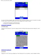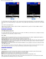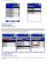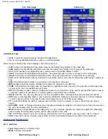
The Jitter Measurement submenu allows the user to measure and analyze received signal jitter. The measurements example is
shown above (the vertical grid spacing is 2.0UIpp). Red Bar is Max. peaked jitter during testing and Yellow is the current peaked
jitter.
Press "Start" to start measurement
Select the HP1+LP (20Hz to 100kHz) or HP2+LP (18kHz to 100kHz) filter for E1, and HP1+LP (10Hz to 400kHz) or HP2+LP
(30kHz to 400kHz) filter for E3
21.8 Wander Measurements
The wander measurements in the PDH Tools section are specific to the TDM rate to which the test set is configured to. Options
and selections may vary depending on selected test rates.
21.8.1 Setup
Clock Port:
Select the appropriate connector or port required to match reference clock interface. Available options depend on
test port configuration and rate. Converter cables may be required in certain cases.
Clock External:
Select the type of signal that matches reference clock signal to be used.
Save TIE to USB:
OFF presents the current real time TIE measurements on screen only. ON sends real time TIE measurements
to an attached USB memory, for further post analysis (refer to the MTIE and TDEV Analysis section). This feature requires the
MTIE and TDEV Post Analysis option.
Sampling Rate:
When Save TIE to USB is ON, this selection indicates how many samples per second are recorded and stored
in the USB memory stick.
Press the Start button to run the test. If Save TIE to USB is set to ON, the test set asks for a file name (keep this into account
when running time-sensitive tests). Do not remove the USB memory stick while the wander test is running.
21.8.2 Results
Current TIE:
Shows the last Time Interval Error (phase error) measured between the reference clock and the test signal.
Max TIE:
Records the maximum TIE value measured since the test was started.
Min TIE:
Records the minimum TIE value measured since the test was started.
MTIE:
Shows the maximum difference between TIE values measured since the test started (Max - Min)
Note:
The wander tests will automatically stop if either of the signals used as reference clock or recovered clock (test signal)
have significant levels of impairments, are lost, or disconnected.
_e-manual_D07-00-051P_RevD00
Содержание VePal TX130M+
Страница 1: ...TX130M _e manual_D07 00 051P_RevD00...
Страница 19: ...Go back to top Go back to ToC TX130M _e manual_D07 00 051P_RevD00...
Страница 69: ...Go back to top Go back to ToC TX130M _e manual_D07 00 051P_RevD00...
Страница 105: ...Go back to top Go back to ToC TX130M _e manual_D07 00 051P_RevD00...
Страница 171: ...Go back to top Go back to ToC TX130M _e manual_D07 00 051P_RevD00...


