


Table of Contents
iv
Gas Meter Calibration .....................................................................................................46
Pulse Rate Setup With FB1 Terminal .............................................................................48
Auto-Calibration using FB1 Terminal ..............................................................................49
Simulation with FB1 Terminal .........................................................................................50
VaporTEK Pump Troubleshooting and Quick Help
Appendix A: VaporTEK System Reference Wiring Diagrams
Figures
VaporTEK System Basic Components
...................................................1
Auxiliary VaporTEK System Components
..............................................2
...............................................................13
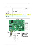
VaporTEK-3 Controller Board Connections
..........................................14
VaporTEK-3 Controller Board Connected To The VaporTEK
Pulse Interface Adapter Board
..............................................................15
VaporTEK Pulse Interface Adapter Board Jumper Settings
VaporTEK Valve Adapter Board Connected To The
VaporTEK-3 Controller board
...............................................................17
VaporTEK Pump Installation Orientations
............................................20
Install The VaporTEK-3 Controller Board Mounting Bracket In
The Dispenser’s Electronic Compartment
............................................21
VaporTEK Pulse Interface Adapter Board Mounted To Back Of
VaporTEK-3 Controller Board Housing
.................................................22
VaporTEK-3 Controller Board Mounting Cover Secured
With Safety Label Affixed.
.....................................................................23
Apply Thermal Transfer Paste To These Component Surfaces
Apply Thermal Transfer Paste To These Component Surfaces
Old Versus New Style VaporTEK Cable Plugs
.....................................25
VaporTEK System - High Voltage Hook Signal Input
VaporTEK System - Liquid Pulse Signal Input
.....................................29
VaporTEK System - Liquid Pulse Signal Input And Monitoring
VaporTEK System – Serial Connection And Monitoring Using
RS422 – Interface With Re-regulation Function.
..................................31
VaporTEK System - Low Voltage Hook Signal With Relay Switch
VaporTEK Low Voltage Relay Diagram
................................................32
VaporTEK High Voltage Relay Diagram
...............................................33
..........................................................34
..................................................................................46
Locate the Burkert Gas Meter Calibration Factor
.................................47
VaporTEK Plus For Collection - Encore 500S With
VaporTEK-3 Controller
....................................................................... A-1
Vaportek System Plus for collection only
W/3 Color LED - Encore 500S Dispenser
........................................... A-2


