Introduction
VaporTEK Controller Pulse Interface (Optional)
15
VaporTEK Controller Pulse Interface (Optional)
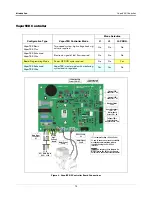
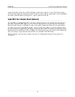
The VaporTEK Pulse Interface Adapter board provides four low-load pulse train inputs to each side of the
dispenser (see Figure 5).
Figure 5. VaporTEK-3 Controller Board Connected To The VaporTEK Pulse Interface Adapter Board
VaporTEK Pulse Interface Adapter Board (P/N 900900-001) Jumpers
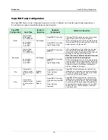
The VaporTEK Pulse Interface Adapter board jumper settings are shown in Figure 6.
Figure 6. VaporTEK Pulse Interface Adapter Board Jumper Settings
VEEDER-ROOT
VAPORTEK-CONTROLLER
900890-001
Rev
.C
P/N 141 031 916
S/N 0000586
D
A
TE 49/2016
RoHS Compliant
PE
F1
PE
L
N
PE
M1
M2
+ - AB SB AA SA
EPV V
A
LV
E
MOTOR
POWER
MOTOR
SIGNAL
J3
V6
V3
V8
V1
X7
X6
X8
PROGRAM
J1
J2
X3
X2
X1
X4
BR1
IC5
RS422
UNSAFE AREA
UNSAFE AREA
SAFE AREA
L1
N
MAIN
230V
L1 N PE
M1 M2
VTEK3-
CTRL
X3
26-Pin Flat
Ribbon Cable
579292-001
VaporTEK-3 Pulse
Interface Adapter
141 086 646
8-24V DC
Pulse Side A
PULS
Power Supply
100W
140 810 856
24V
DC
OK
L
N
+ +
+ +
GND
GND
P4A
P3A
P2A
P1A
GND
GND
P4B
P3B
P2B
P1B
Pulse Side B
To the encoder lines
of target dispenser
VTEK3-
CTRL
X3
8-24VDC
Power
To VaporTEK-3 Controller
Board Pulse Interface Port X8
LED’s Pulse Channel
1A 2A 3A 4A 1B 2B 3B 4B
Pulse Inputs
Side A
Pulse Inputs
Side B
GND
GND
P4A
P3A
P2A
P1A
GND
GND
P4B
P3B
P2B
P1B
+
+
-
-
141 086 646
1 2 3
1 2 3
1 2 3
P4B - Pulse Input
P4A - Pulse Input
P4B - Diesel Disable
P4A - Diesel Disable
1 2 3
J1 and J2 Jumper Positions


