27
Wiring Schematics
VaporTEK Wiring
1.
Depending on the configuration used to actuate the pump, follow steps 2,3 and 4.
2.
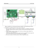
VaporTEK with High Voltage Hook Signal (see Figure 15)
a.
Refer to the dispenser manufacturer’s manual, to determine where to tap into the 110-230 VAC hook
signal. Using the 18AWG, 2 conductor cable included in the VaporTEK-3 Controller Kit, connect the hook
signal from Side A to M1 on the VaporTEK-3 Controller board and connect the hook signal from Side B to
M2.
3.
VaporTEK with Pulse Signal for Non E500S Dispensers
-
Requires VaporTEK Pulse Adapter Interface (see
a.
The VaporTEK Pulse Adapter Interface board can be connected to a maximum of 4 pulse signals per side.
b.
Connect the pulse signal to the VaporTEK Pulse Interface using the 24AWG, 8 conductor signal cables
included in the Kit. (Note: 2 conductors used per pulse signal input, see wiring diagram in Figure 17.
c.
A monitoring system can be connected to the RS422 - X4 Interface using a 10 pin ribbon cable. To
establish communication with the monitoring system, Jumpers J1 and J2 need to be in place on the
VaporTEK-3 Controller board (see Figure 4 on page 14). After power up the VaporTEK-3 Controller board
starts to communicate to the connected monitoring system automatically.
4.
VaporTEK with RS422 –Serial Connection
All information like fuel flow, Monitoring status and re-regulation will be exchanged using a 10-pin standard
ribbon cable (see Figure 18).
5.
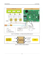
VaporTEK with Low Voltage hook signal with relay switches (see Figure 19).
a.
Refer to the dispenser manufacturer’s manual to determine the dispenser type (Blended or Multi product),
the number of available nozzle hooks and where to tap into the hook signal (verify the low voltage hook
signal voltage rating is 3-32 VDC).
b.
Using the 18AWG, 2 conductor cable from the kit, connect each nozzle hook signal on Side A of the
dispenser to one relay circuit.
c.
A high voltage source (110-230VAC) is connected to M1 on the VaporTEK-3 Controller board through all
the relay circuits on Side A (See Figure 20) for low voltage relay wiring diagrams).
d.
Make similar connections on Side B and connect to M2 on the VaporTEK-3 Controller. board.


