Wiring Schematics
VaporTEK Wiring
30
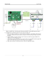
Figure 17.
VaporTEK System - Liquid Pulse Signal Input And Monitoring
-B+ -A+
Pulse
Out B
-2 + -1+ - +
Out A
5 V
B A
B
A
1 2 3 4 5 6 7 8
1 2 3 4 5 6 7 8
PE N L
RS485
230 V~
RS485-4
- 2+ -1+
FAFNIR
VAPORIX - Control
S
ervice
VAPORIX Flow -
SIDE A
VEEDER-ROOT
VAPORTEK-CONTROLLER
900890-001
Rev
.C
P/N 141 031 916
S/N 0000586
D
A
TE 49/2016
RoHS Compliant
F1
PE
L
N
PE
M1
M2
+ - AB SB AA SA
EPV V
A
LV
E
MOTOR
POWER
MOTOR
SIGNAL
J3
V6
V3
V8
V1
X7
X6
X8
PROGRAM
J1
J2
X3
X2
X1
X4
BR1
IC5
RS422
UNSAFE AREA
UNSAFE AREA
SAFE AREA
L1
N
MAIN
230V
L1 N PE
FB1 Service Terminal
F6
F1
F8
F3
Home
7
END
1
•
SHIFT
SPACE
ENTER
INS
0
—
+
2
PgDn
3
4
5
6
PgUp
9
8
F9
F4
F10
F5
F7
F2
START
VTEK3-
CTRL
X3
26-Pin Flat
Ribbon Cable
579292-001
VaporTEK Pulse
Interface Adapter
141 086 646
8-24V DC
Pulse Side A
PULS
Power Supply
100W
140 810 856
24V
DC
OK
L
N
+ +
+ +
Pulse Side B
To the encoder lines
of target dispenser
RS485
Interface
Optional
Kiosk Alarm Indicator
VAPORIX Flow -
SIDE B
For calibration purposes, remove the Vaporix
cable and attach FB1 Service terminal here.
PE
M1 M2
GND
GND
P4A
P3A
P2A
P1A
GND
GND
P4B
P3B
P2B
P1B


