


Installation
VaporTEK-3 Controller and VaporTEK Pulse Interface Installation
22
VAPORTEK PULSE INTERFACE ADAPTER BOARD INSTALLATION
1.
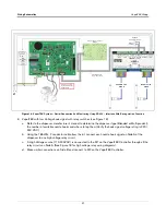
Mount the VaporTEK Pulse Interface board to the back of the new sheet metal bracket 900892-001 with the
four stand offs (579081-001) from the kit (see item 1 ([typical 4 corners], Figure 10).
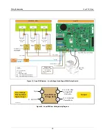
Figure 10. VaporTEK Pulse Interface Adapter Board Mounted To Back Of VaporTEK-3 Controller Board Housing
2.
Plug the 24V input cable wires into the terminal plug (item 2) on the VaporTEK Adapter Interface board The +
to wire connects to a + terminal and the negative wire to a negative (-) terminal. Note: terminal polarities are
stenciled on the board beneath the plug.
3.
To get 1 grade pulse input for Side A, insert cable 900643-001 to P1A and GND terminals to the board as
shown (Item 3). For additional grades utilize additional ports.
4.
To get 1 grade pulse input for Side B, insert cable 900643-001 to P1B and GND terminals to the board as
shown (Item 4). For additional grades utilize additional ports.
5.
Plug the 26-Pin Flat Ribbon Cable (P/N 579292-001) plug (Item 5) to the board as shown.
6.
Get the
VaporTEK-3 Controller board MTG Cover, P/N 900893-001 from the
VaporTEK-3 Controller Board Kit - P/N
900895-001. Notice the two slots in the left side of the housing (item 7). The two bent tabs on the left side of
the cover will hook into the tabs and swing from left to right covering the housing. A single tab on the right
side of the cover will line up over the PEM nut in the right side of the housing (item 8). Screw the second pan
head Phillips screws, M4-0.7 X 12LG/Lock washer M4, P/N 579198-001 from the kit into the PEM nut to
secure the door over the housing (see Figure 11).
1
2
3
4
5


