Installation
VaporTEK-3 Controller and VaporTEK Pulse Interface Installation
21
VaporTEK-3 Controller and VaporTEK Pulse Interface Installation
WARNING! Before installing these components, turn off, tag/lock out power to the dispenser
until all steps in this section are complete.
The VaporTEK-3 Controller and VaporTEK Pulse Interface board must be installed in the non-
hazardous location of the dispenser (unclassified area), and protected from weather.
VAPORTEK-3 CONTROLLER BOARD INSTALLATION
1.
Mount the VaporTEK-3 Controller board bracket to a clean sheet metal surface in the dispenser’s electronic
compartment using the two
SHCS, M6X1 X 20MM LG, Grade 8.8; P/N 579281-001
bolts and two
Hex Nut, M6 X 1,
Steel, P/N 579082-001
nuts from the VaporTEK-3 Controller Board Kit - P/N 900895-001 (see item 1
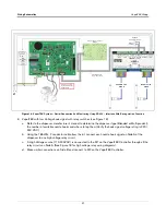
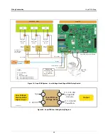
Figure 9. Install The VaporTEK-3 Controller Board Mounting Bracket In The Dispenser’s Electronic Compartment
2.
Plug in the ribbon cable connector that connects to the VaporTEK Pulse Interface Adapter board into the X8
male connector on the VaporTEK-3 Controller board (see item 2 in Figure 9).
3.
Plug in the Motor Power 4-pin snap plug (item 3) and the Motor Signal 6-pin snap plug (item 4) from the
VaporTEK pump.
4.
Plug in the input power plug (L, N and Earth Ground) (item 5).
5.
Attach the ground wire from the Motor Power cable and the Earth Ground wire from the input power cable to
the VaporTEK-3 Controller board at the location shown (item 6), using one of the pan head Phillips screws,
M4-0.7 X 12LG/Lock washer M4, P/N 579198-001 from the kit. There is a PEM nut under the board which
receives the screw.
OFF
1
1
2
3
4
5
6
7
7
8


