CB-800
CB-1000
2.14 M
ACHINE
A
SSEMBLY
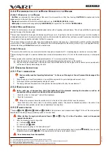
Please request your machine set-up and training from your dealer as part of the pre-sales service.
Due to the weight of the machine, its assembly should be carried out with two workers.
•
The machine is delivered in two boxes - the machine base is in the box marked
A
, the brushes in the box marked
B
.
Fig. 32
on page
1.
Remove all loose machine parts from box
A
and the brushes from box
B
.
2.
Sort the fasteners from the bag with Operating Instructions.:
3.
Cut the box at all four corners and fold the sides and fronts down.
4.
Cut the plastic strips that fix the handlebars
7
on the cardboard insert. Remove the cardboard insert.
5.
Lift the machine up slightly by pulling on the handlebar holder
8
. The other worker will remove the cardboard insert under the
machine axle.
6.
>1
and
>2
: The other worker puts flat washers
1
21 mm
2
, lubricates the axle shaft ends and fits the left wheel
3
and
right wheel
4
. He will secure the wheels with their locking pins with caliper
5
and locking rings
6
.
Make sure the wheel tread direction matches the image in
Fig. 32
. The wheel direction arrow on the side of the tyre labelled
ROTATION
.
7.
Lower the machine onto the wheels.
8.
Lift and turn the handlebars by 180°.
Make sure the Bowdens are not crossedd!
9.
>3
: Fit the handlebars
7
to the handlebar tubular bracket
8
, insert the bolt from the left
9
, insert the flat washer 8.4
mm
10
, lightly lubricate the bolt tread end. Screw on the plastic star
11
and tighten it securely.
10. Secure the Bowdens via two plastic tie straps
12
to the handlebar handles
7
at the point before the first tube bend. Jointly
fasten the throttle Bowden and brush drive actuation Bowden to the right handlebar handle.
11.
>4
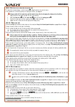
: Lubricate the thread in the support wheel. Insert the support wheel
13
from below into the square tube
14
to the
extreme position. Turn the control knob a few times
15
to the right, so the support wheel engages with the control knob screw.
The machine will stand on its own now.
12.
>5
: To the support plate on the brush drive
16
via screws
17
with nuts
18
and inserted rubber columns
19
attach the
brush position setting lever
20
. Tighten the screw connection, so the rubber columns
19
get only slightly compressed.
13.
>6
: To the support plate on the brush drive
16
Using the screw connection,
B
attach the connecting sheet metal part
23
.
14.
>6
: Depending on the selected brush width (see
Fig. 31
) Screw the fenders onto the brush drive support plate
16
21
and
22
via the screw connections
A
and
B
. The flat washer in screw connection
B
must always be under the screw head on the
plastic fender side.
15.
>7
: Slide the bolt into the hole in the square
24
drift tube
25
. Slide the bolt into the hole in the hexagonal output shaft
26
of the brush drive. Slide the square drift tube
24
onto the hexagonal output shaft
26
. Slide the other drift square tube
27
,
screw on the self-locking collar nut
28
. Tighten securely.
16. Follow the procedure in
Chap. 2.7.5 Brush change
on page
and
Fig. 27
Attach your selected brush width.
40
re
vi
ze
1
2/
20
21


