CB-800
CB-1000
2.11 H
OW
TO
O
RDER
S
PARE
P
ARTS
The spare parts list is not part of these operating instructions.
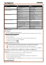
For correct identification of your device, you have to know the type designation (
Type
), serial identification number (
№
) and order number (
C№
)
stated on the nameplate of the device, on the box or in the warranty card. Only with this information can the exact designation of the relevant spare
part be traced to your dealer.
To search spare parts in the electronic catalogue of spare parts at
, the first 10 characters of the identification number
(
№
) are sufficient. If you do not have Internet access, you can ask for the printed catalogue to be sent C.O.D.
Field
Description
Type
Device type designation
CB-800/CB-1000
№
Unique serial identification number:
1006600176.1121.00001
(product.period.sequence)
C№
Business (order) number:
4588/4591
Table 22: Nameplate - example
2.12 M
ANUFACTURER
’
S
C
ONTACT
I
NFORMATION
VARI, a.s.
Phone: (+420) 325 607 111
Opolanská 350
Fax: (+420)
325 607 264
289 07 Libice nad Cidlinou
E-mail:
The Czech Republic
Web:
2.13 A
TTACHED
ILLUSTRATIONS
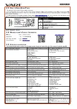
The attached illustrations are common for all language versions they can be found at the end of this manual in Chapter
.
Fig. 1: Main Machine Components
Fig. 2: Handlebar settings, binding and grip points
Fig. 3: Machine Control Elements
Fig. 4: Accelerator lever position
1 STOP position
The engine is not running.
- Engine switch-off.
- Engine shutdown.
- Refuelling.
- Machine transport.
3 “Rabbit” position MAX
The engine runs at its maximum speed.
- Working position.
2 “Turtle” position MIN
The engine runs at its idle speed.
- Short break.
4 CHOKE position
The engine choke is engaged.
- Cold engine start.
Fig. 5: Slower travel - turtle
Fig. 6: Faster travel - rabbit
Fig. 7: Cover removal
Fig. 8: Sticker - speed selection
Fig. 9: Wheel drive disconnecting
Fig. 10: Adjusting the brush pressure
Fig. 11: Adjustment when parking / storing the
machine
Fig. 12: Adjusting the sweeping rollers position
Fig. 13: Collection box fitting
Fig. 14: Discharging dirt from the collection box
Fig. 15: Collection box transport position
Fig. 16: Sweeping plough fitting
Fig. 17: Fitting the anti-dust sheet to the machine
Fig. 18: Fitting the snow chain to the wheel
Fig. 19: Threaded handlebar mounting bolt
Fig. 20: Sweeper roller drive pulley
Fig. 21: Travel pulley
Fig. 22: Handlebar Bowdens
Fig. 23: Bowdens on the frame rear
Fig. 24: Sweeper roller gearbox mount
Fig. 25: Support wheel extraction control
Fig. 26: Support wheel
Fig. 27: Sweeping roller replacement
Fig. 28: Bowden and tension pulley adjustment
screws
Fig. 29: V-belt tracks and guide pins
1 Brush drive V-belt
2 Gearbox drive V-belt
3 Axle drive V-belt
4 Brush drive pulley
5 Travel drive pulley
6 Drive pulley on the engine
7 Driven pulley on the brush drive
8 Driven gearbox on the gearbox
9 Double drive travel pulley
10 Double driven travel pulley
11 Gearbox belt tensioner
12 Directional pulley
13 Front belt guides
14 Crossbar belt guides
15 Belt guides under the engine
Fig. 30: Travel V-belt change
1 Right wheel
2 Left wheel
3 Axle
4L 4R Side protective covers
5 Connecting bar
6 Axle bearing body nut
7 V-belt
Fig. 31: Conversion to a different sweeping width
Fig. 32: Machine Assembly
Fig. 33: Sticker - speed selection
Fig. 34: Combined sticker
Fig. 35: Sticker - brush pressure adjustment
Fig. 36: Sticker - brush drive switching
Safety stickers - machine locations
Fig. 37: Sticker - travel actuation
Fig. 38: Tools and accessories – not included in the
machine
Spark plug wrench 21 mm (3/8")
Ratchet handle 3/8“
12-point socket 3/8“ 15 mm
VARI canister Order No. 3562
HONDA fuel stabiliser Order No. 08CXZ-FSC-250
Briggs & Stratton Fuel Fit
TM
Fuel Stabiliser (Order
No. 992381)
VARI POWERMETER engine hour meter Order. No.
4227
39
re
vi
ze
1
2/
20
21


