background image

7

Installation and maintenance manual atmoCRAFT


GB

Safety instructions and regulations

3.1 Safety 

instructions

Assembly

The combustion air fed to the unit must be free of 
chemicals which contain, e.g. fluorine, chlorine or 
sulphur. Sprays, solvents or cleaning agents, paints and 
adhesives can contain such materials which can, in 
certain circumstances, lead to corrosion when operating 
the unit, including the exhaust gas installation.
In business premises such as hairdressing salons, 
painting or carpentry workshops, cleaning businesses 
etc., also when operating in room-air independent mode, 
a separate room must always be used for the installation 
which will ensure that the supply of combustion air is 
technically free from chemicals.
It is not necessary to keep a clearance between the 
appliance and combustible materials or components, as 
at the rated heating power of the appliance, the 
temperature here is always lower than the permitted 
temperature of 85 °C.
Clearances in accordance with Section 4.3 must be 
maintained for maintenance purposes.

Note concerning flue design:

The double stage system of the boiler with combustion 
air matching produces high values of combustion 
technological effectivity. This requires technical evidence 
of the suitability of the flue in according with the 
relevant standards.

Installation

Before the installation of the boiler, the comments of the 
gas supply company and the district chimney sweep 
must be obtained.
The boiler may only be installed by a suitably qualified 
heating engineer. who also assumes the responsibility 
for installing the appliance properly and putting it into 
service for the first time.

Flush the heating system thoroughly before connecting the 
appliance! By doing that, residue such as welds, cinder, 
hemp, putty, rust, rough dust and similar substances are 
removed from the pipes. Otherwise such substances can be 
deposited in the appliance and cause damage.
Make sure that the connection and gas pipes are not 
under stress when installed to avoid leakage in the 
heating installation or in the gas connection!
To tighten or loosen bolts, only use suitable open-ended 
spanners (do not use pliers or extensions etc.). Improper 
use or unsuitable tools can cause damage, such as gas 
or water leaks.
On closed heating installations, a type-approved safety 
valve corresponding to the heat capacity must be fitted.
The gas regulating block may be tested for leakage only 
with a maximum pressure of 50 mbar! Higher testing 
pressures can damage the gas fitting.

The electrical installation may only be performed by a 
heating engineer.
There is a danger to life by electrocution from current-
carrying components! The supply terminals in the 
terminal box of the device are under voltage even if the 
mains switch is off. Before working on the appliance, 
turn off the power supply and secure against restart.

Important instructions for propane appliances

Bleeding the liquid gas tank when installing the system:
before installing the device, make sure that the gas tank 
has been bled. The liquid gas supplier is responsible for 
the proper bleeding of the tank. Ignition problems can 
be caused if the tank is not bled properly. In such cases, 
first contact the person in charge of filling the tank.

Affix tank sticker:

Affix the enclosed tank sticker (propane quality) on the 
tank where it is clearly visible, if possible close to the 
filler nozzle.

Start-up

Do not add frost or corrosion preventative to the 
heating water! If frost or corrosion preventative is added 
to the heating water this can cause changes in the seals 
and can cause noises to be created during the heating 
process. Vaillant assumes no liability for this and such 
consequential damages. Please inform the user of the 
procedure for frost protection. If the heating water 
hardness is above 3,6 mol/m

3

 (20 °dH) it should be 

softened. To do this you can use the ion-exchanger, 
Vaillant spare part number 990 349. Please observe the 
enclosed operating instructions.

For natural gas:

If the connected pressure is outside the range 17 to 
25 mbar, the unit must not be operated!

For liquid gas: (37 mbar)

If the connected pressure is outside the range 35 to 
45 mbar, the unit must not be operated!

Inspection and maintenance

Inspection, maintenance and repair work should only be 
undertaken by an approved heating installation company. 
Inspections / Maintenance work not carried out can result 
in damage to property and personal injury.
Risk of fatal electric shock from touching live 
connections! The supply terminals in the terminal box of 
the device are under voltage even if the mains switch is 
off. Before working on the appliance, turn off the power 
supply and secure against restart.
Protect the switch box from water splashes.
Danger of explosion through gas leakage! The mixer tube 
between the gas control unit and burner must not be 
opened. It can only be guaranteed that this component is 
gas-proof after it has been checked at the factory.

Safety instructions and regulations 3

Содержание atmocraft

Страница 1: ...VK 654 9 1654 9 atmoCRAFT DE AT GB...

Страница 2: ......

Страница 3: ...For the heating engineer VK 654 9 1654 9 Installation and maintenance instructions atmoCRAFT Gas heating boiler GB...

Страница 4: ...its 24 5 4 6 Connecting external sensors control units accessories 25 6 Start up 25 6 1 Filling the installation 25 6 1 1 Water preparation in heating installations 25 6 1 2 Preparing for operation 26...

Страница 5: ...364 The manuals for any accessories and controllers used also apply Auxiliary service equipment The following test and measuring equipment are required for inspection and maintenance CO2 measuring ins...

Страница 6: ...s responsible for adhering to the existing regulations rules and guidelines 2 4 Structure of atmoCRAFT The Vaillant atmoCRAFT gas boilers are used generate heat for hot water central heating systems a...

Страница 7: ...Designated country designation in accordance with ISO 3166 Approval category Type of gas VK 654 9 VK 754 9 VK 854 9 VK 1054 9 VK 1154 9 VK 1304 9 VK 1504 9 VK 1654 9 65 0 80 60 C 75 0 80 60 C 85 0 80...

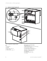
Страница 8: ...mersion sleeve 6 Safety temperature limiter STL Operating elements of the control box 7 Main ON OFF switch 8 Digital information and analysis system with display 9 Feed temperature controller 10 Stora...

Страница 9: ...ck may be tested for leakage only with a maximum pressure of 50 mbar Higher testing pressures can damage the gas fitting The electrical installation may only be performed by a heating engineer There i...

Страница 10: ...nts of the Local Authority Building Regulations The Building Regulations Scotland The Building Regulations Northern Ireland and the relevant recommendations of the following British Standards BS 6700...

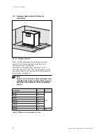
Страница 11: ...ntenance purposes If the boiler is to be installed on a flammable floor e g wood PVC or similar the boiler must be placed on an underlay of non flammable material 4 1 2 Notes concerning the heating sy...

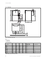
Страница 12: ...s connection Boiler Type A B C d Heating feed Heating return Gas connection 65 kW 850 860 960 180 R 1 1 2 R 1 75 kW 930 850 960 200 R 1 1 2 R 1 85 kW 1010 850 960 200 R 1 1 2 R 1 105 kW 1170 838 960 2...

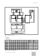
Страница 13: ...1304 1830 1950 1773 180 250 310 980 1048 1600 130 I 1600 VKM 1504 1990 1950 1773 200 280 270 1060 1038 1600 130 I 1600 VKM 1704 2070 1950 1773 200 280 270 1060 1038 1600 50 I 1600 VKM 2104 2470 1986 1...

Страница 14: ...of the boiler room should be at least 2200 mm also with VKM The side clearances and the clearance in front of the unit shown in the drawing are for maintenance purposes Note Please bear in mind that...

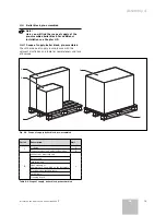
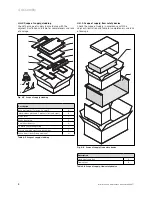
Страница 15: ...of supply in accordance with the adjacent illustration and table for completeness and lack of damage A B 1 2 C Fig 4 4 Scope of supply boiler block pre assembled Pallet Description Unit 1 Cladding A F...

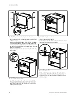
Страница 16: ...ackets left and right B White cover C White front plate D 2 x white side parts A 1 x white ventilation grating F Cross beam with electronic box holder G Loose items bolts fixing elements H Table 4 5 S...

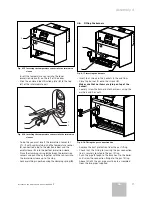
Страница 17: ...can be considerably higher 4 5 Installation of ancillary components 1 Fig 4 8 Fitting the brackets Bolt the two brackets 1 right and left to the baseframe 1 2 Fig 4 9 Fitting the flow safety device Pl...

Страница 18: ...tes to the intermediate plate at the top with screws 2 1 Fig 4 12 Fitting the cross beam Insert the projections 1 on the cross beam 2 into the openings in the side plates and screw the cross beam to t...

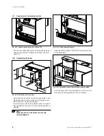
Страница 19: ...n the immersion sensors and push them together with the sensors into the immersion sleeve up to the stop Lock everything in position using the clamping spring 5 4 6 Fitting the burners 1 1 2 2 Fig 4 1...

Страница 20: ...cle in the side plates and secure it with one self tapping screw 2 on the left and right hand sides Insert the braces 3 of the additional back wall plates 4 and 5 into the back wall and screw both pla...

Страница 21: ...cover plate is in line with the side plates 1 Fig 4 24 Fitting the exhaust gas pipe Push the exhaust gas pipe to be provided by the customer 1 onto the flow safety device Note Make sure that the exha...

Страница 22: ...k may be tested for leakage only with a maximum pressure of 50 mbar Higher testing pressures can damage the gas fitting Check the gas connection with leak indicator spray for leakage 5 3 Heating side...

Страница 23: ...Pro E in the boiler Connect the mains feed securely to the ProE plug see Fig 5 1 5 4 3 Connecting the sensors and setting motors 3 2 1 4 5 6 Fig 5 2 Connecting the sensors and setting motors Connect t...

Страница 24: ...herwise replacement resistance Storage tank sensor accessories Boiler sensor Coded resistance 12 7 kOhm Feed return sensor option DCF connection External sensor Remote control circulation pump Mass ET...

Страница 25: ...esistance Storage tank sensor accessories Boiler sensor Coded resistance 12 7 kOhm Feed return sensor option DCF connection External sensor Remote control circulation pump Mass ET plug 252629 Mass Plu...

Страница 26: ...al display and External heating pump and Control circulation pump and Control of an external exhaust gas diverter The accessories are and ancillary connection box which contains the functions referred...

Страница 27: ...on 6 1 1 Water preparation in heating installations Requirements for the quality of the filling and top up water in accordance with VDI 2035 Heat generators with output up to 100 kW Water having a car...

Страница 28: ...e the customer acquainted with the operation of the unit and hand over the instruction manual associated with the unit for suitable storage Recommend a maintenance contract to the customer 6 2 Checkin...

Страница 29: ...gas distributor pipe Open the gas shut off cock again Start the boiler up in accordance with Chapter 6 Setting the 1st stage Change the boiler over via the diagnosis point d 00 to operation of the 1st...

Страница 30: ...al output partial output Nozzle pressure in mbar at 15 C 1013 mbar dry VK 654 9 VK 754 9 VK 854 9 VK 1054 9 VK 1154 9 Nominal output partial output2 65 42 2 75 48 7 85 55 2 105 68 2 115 74 7 Gas flow...

Страница 31: ...burner nozzles for natural gas 2 and screw in the burner nozzles for liquid gas P 165 gas tight 1 Fig 6 4 Pipe connection with stop cock Fit the pipe connection with stop cock 1 onto the gas fitting C...

Страница 32: ...ucted or retricted The recommended chimney draught must be at least 0 03 mbar and must not exceed 0 09 mbar Note The lower the chimney draught within the permissible range the higher is the combustion...

Страница 33: ...does not affect the customer s statutory rights 7 Adapting the appliance to the heating system The atmoCRAFT units are fitted with a digital information and analysis system DIA system 7 1 Selection a...

Страница 34: ...et value Display in C d 16 Changeover external pump solar pump 2 Normal mode 2 d 46 External temperature correction value For correction of external heat effects on the sensor 10 10 K 0 K d 50 Switch...

Страница 35: ...perform the following steps after completing any inspection tasks Close the heating feed and return If necessary refill the device with hot water up to a pressure of approx 1 5 bar and evacuate the he...

Страница 36: ...empt the automatic gas combustion unit switches to fault The error message F 29 appears in the display Re insert the plug of the ionisation cable The boiler can be unlocked after approx five seconds s...

Страница 37: ...nt cover Release the connection screws on the gas inlet line Caution Always replace the seals by new original ones when assembling Remove the ignition cable connection from the electronic box Remove t...

Страница 38: ...supplied 2 You can access the exhaust gas ducts through the cleaning aperture in the exhaust gas manifold Re fit the burner again see Section 8 4 1 Caution After cleaning the gas and exhaust gas route...

Страница 39: ...gas setting F 29 Fault in continuous operation Flame goes off during operation and subsequent ignition attempts failed Gas supply temporarily stopped ignition transformer has spark failure faulty eart...

Страница 40: ...e Displays during storage tank charging Page 20 Storage cycle mode active S 23 Storage tank charging ignition S 24 Storage tank charging burner S 27 Storage tank charging pump overrun S 28 Burner bloc...

Страница 41: ...tch off hysteresis of feed controller Setting range 0 10 factory setting 6 d 51 Switch on hysteresis of feed controller Setting range 0 10 factory setting 2 d 60 Number of temperature limiting shutdow...

Страница 42: ...as environmental hazards and health risks during recycling and the disposal of unavoidable remains of unusable residue 11 1 Appliance The Vaillant boiler consists of 92 metallic materials which can b...

Страница 43: ...3 35 83 35 83 35 83 35 83 35 83 35 83 Connection values Natural gas E Hi 9 5 kWh m3 m3 h 7 4 8 5 9 7 11 9 13 14 9 17 18 8 Liquid gas P Hi 12 8 kWh kg 2 kg h 5 5 6 3 7 2 8 8 9 7 11 12 7 14 Gas connecti...

Страница 44: ...835553_02 DEATGB 092006...

Отзывы: