18
Installation and maintenance manual atmoCRAFT
4.7
Connection of the electrical cable
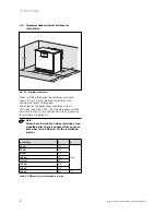
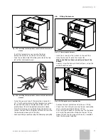
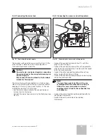
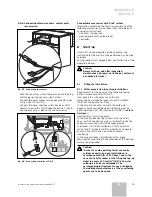
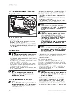
Fig. 4.19 Connecting the gas valves and the STL
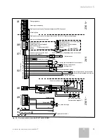
• Connect the connection cable to the electronic box as
shown in the electrical schematic drawing, see 5.4.3
and 5.4.4.
4.8
Completing the boiler
1
2
4
5
3
3
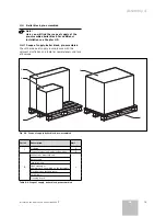
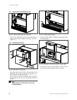
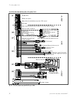
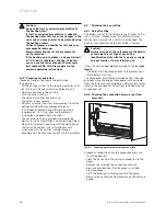
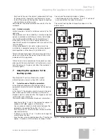
Fig. 4.20 Fitting the back wall plate
• Hang the back wall plate (
1
) into the receptacle in the
side plates and secure it with one self-tapping screw
(
2
) on the left and right hand sides.
• Insert the braces (
3
) of the additional back wall plates
(
4
) and (
5
) into the back wall and screw both plates in
position.
Note!
Make sure that all the plates are securely
screwed together.
1
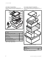
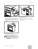
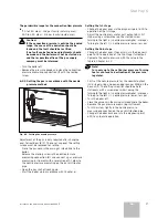
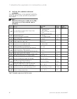
Fig. 4.21 Fitting the plinth adaptor
• Hang the plinth adaptor (
1
) into the lateral receptacles
in the side pieces.
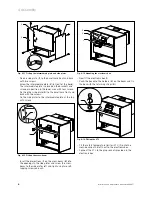
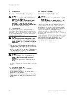
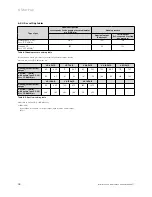
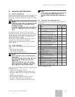
Fig. 4.22 Placing the cover of the electronic box in position
• Push the cover over the electronic box so that it clicks
into place on the projection on the cross-beam.
4 Assembly
Содержание atmocraft
Страница 1: ...VK 654 9 1654 9 atmoCRAFT DE AT GB...
Страница 2: ......
Страница 44: ...835553_02 DEATGB 092006...

