background image

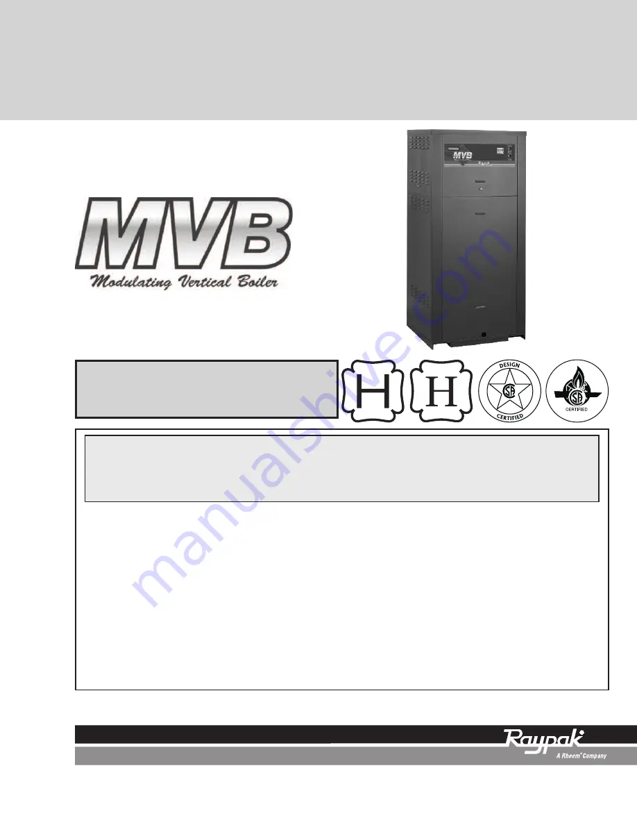
INSTALLATION & OPERATING

INSTRUCTIONS

CATALOG NO. 3400.54E

Effective: 03-25-10

Replaces: 03-19-09

P/N 241317 Rev. 6

This manual should be maintained in legible condition and kept adjacent to the heater or in a safe place for future

reference.

Models

504–2004

Types H, WH, P & WHP

L

W

WHAT TO DO IF YOU SMELL GAS:

• Do not try to light any appliance.

• Do not touch any electrical switch; do not use any phone in your building.

• Immediately call your gas supplier from a neighbor's phone. Follow the gas

supplier's instructions.

• If you cannot reach your gas supplier, call the fire department.

WARNING:

Improper installation, adjustment, alteration, service or maintenance can

cause property damage, personal injury, exposure to hazardous materials* or loss of

life. Review the information in this manual carefully. *This unit contains materials that

have been identified as carcinogenic, or possibly carcinogenic, to humans.

FOR YOUR SAFETY:

Do not store or use gasoline or other flammable vapors and

liquids or other combustible materials in the vicinity of this or any other appliance. To

do so may result in an explosion or fire.

Installation and service must be performed by a qualified installer, service agency or

the gas supplier.

Summary of Contents for MVB H-1104

Page 1: ...ructions If you cannot reach your gas supplier call the fire department WARNING Improper installation adjustment alteration service or maintenance can cause property damage personal injury exposure to hazardous materials or loss of life Review the information in this manual carefully This unit contains materials that have been identified as carcinogenic or possibly carcinogenic to humans FOR YOUR ...

Page 2: ...text changes on page 20 Fig 21 on page 22 Figs 22 28 on pages 25 30 Table N on page 29 Fig 35 on page 32 Mode 8 description on page 33 minor text changes on pages 42 43 and 46 Troubleshooting chart on page 48 Additions Fig 2 on page 6 Low lead requirement on page 5 Fig 8 on page 11 note on page 12 Caution on page 20 Fig 22 on page 22 Fig 36 on page 33 air filter instructions on pages 50 and 51 ...

Page 3: ...ons 20 Field Wiring Connection 22 Venting 22 Venting Installation Tips 24 Venting Configurations 24 Engineered Vent Systems 27 Outdoor Installation 29 Controls 30 Heater Sequence of Operation 37 WIRING DIAGRAMS 40 START UP 42 Pre Start up 42 Start Up 43 OPERATION 46 Lighting Instructions 46 To Turn Off Gas To Appliance 47 UDB Fault History 47 TROUBLESHOOTING 48 MAINTENANCE 49 Suggested Minimum Mai...

Page 4: ... liquids and vapors Heater should never be covered or have any blockage to the flow of fresh air to the heater WARNING CALIFORNIA PROPOSITION 65 This product contains chemicals known to the State of California to cause cancer birth defects or other reproductive harm WARNING Risk of electrical shock More than one disconnect switch may be required to de energize the equipment before servicing CAUTIO...

Page 5: ... The model identification number and heater serial number are found on the heater rating plate located on the upper rear jacket panel of the heater The model number will have the form H7 2004 or similar depend ing on the heater size and configuration The letter s in the first group of characters identifies the application H Hydronic Heating P Pool Heating WH Domestic Hot Water DHW WHP Water Heater...

Page 6: ...in omitted for clarity Fig 4 Component Locations Top Fig 3 Component Locations Rear Model No MBTUH Input Water Conn NPT Gas Conn NPT Vent Size in Max Min N P Flue Intake 504 500 350 2 1 1 8 6 754 750 525 2 1 1 10 6 1104 1100 770 2 1 2 1 1 4 1 10 6 1504 1500 1050 2 1 2 1 1 4 1 12 8 2004 1999 1400 2 1 2 2 1 14 8 H7 units only Panels omitted for clarity Fig 2 Component Locations Front ...

Page 7: ...temperatures occur just after the heater s burner has shut off To determine the water temperature being delivered turn on a hot water faucet and place a thermometer in the hot water stream and read the thermometer NOTE When this water heater is supplying general purpose hot water for use by individuals a thermostatically controlled mixing valve for reducing point of use water temperature is recomm...

Page 8: ...lations INSTALLATION INSTALLATION Installation Codes Installations must follow these codes Local state provincial and national codes laws regulations and ordinances National Fuel Gas Code ANSI Z223 1 NFPA 54 latest edition NFGC National Electrical Code ANSI NFPA 70 latest edition NEC Standard for Controls and Safety Devices for Automatically Fired Boilers ANSI ASME CSD 1 CSD 1 when required For Ca...

Page 9: ...r Indoor Units This heater must be supplied with sufficient quantities of non contaminated air to support proper combustion and equipment ventilation Combustion air can be sup plied via conventional means where combustion air is drawn from the area immediately surrounding the heater or via direct vent where combustion air is drawn directly from outside All installations must com ply with the requi...

Page 10: ...ce 4 ft 1 2m below or to side of opening 1 ft 30 cm above opening 3 ft 91 cm K Clearance to mechanical air supply inlet 3 ft 91 cm above if within 10 ft 3m horizontally 6 ft 1 83m L Clearance above paved sidewalk or paved driveway located on public property 7 ft 2 13m 7 ft 2 13m t M Clearance under veranda porch deck or balcony 12 in 30 cm TT 1 In accordance with the current ANSI Z223 1 NFPA 54 Na...

Page 11: ...e of the duct The screen assembly should be removed before attaching any air duct to the heater The screws and duct connection point must be sealed with RTV not supplied TruSeal is generally used when dam aging contaminants are present in the mechanical room All ducting must be self supported Conventional Combustion Air Supply U S Installations All Air from Inside the Building The confined space s...

Page 12: ...ors Canadian Installations 2 For heaters using a barometric damper in the vent system there shall be a permanent air supply opening s having a cross section area of not less than 1 in 2 per 7 000 BTUH 320 mm2 per kW up to and including 1 million BTUH plus 1 in 2 per 14 000 BTUH 160 mm2 per kW in excess of 1 million BTUH This opening s shall be either located at or ducted to a point not more than 1...

Page 13: ...bypass acting as the secondary boiler piping Raypak strong ly recommends that thermometer s be placed into the heater piping next to the in out header to facilitate tem perature adjustment Inlet water temperatures below 120 F 49 C can excessively cool the products of combustion resulting in collection of condensate in the heat exchanger area beyond the capacity of the con densate evaporation syste...

Page 14: ...er is kept in a narrow temperature range of no more than 10 F 5 C a permanent manual bypass can be employed and manually adjusted to achieve an inlet temperature of 120 F 49 C or higher as adjusted at the minimum temperature in this narrow temperature range i e Range 75 F to 85 F adjust bypass with temperature at 75 F 24 C so that when temperature is 85 F 29 C minimum inlet temperature would be 13...

Page 15: ...ater water during the cooling cycle It is highly recommend ed that the piping be insulated Air Separation Expansion Tank All heaters should be equipped with a properly sized expansion tank and air separator fitting as shown in Fig 11 Fig 11 Air Separation Expansion Tank THERMOSTAT OR SYSTEM SENSOR Fig 12 Single Heater Low Temperature Heat Pump Application with Primary Secondary Piping THERMOSTAT O...

Page 16: ...r gallon a water softener treatment system must be utilized Caution For scale free operation with Hard Water 16 25 grains per gallon of total hardness the operating control must NOT be set higher than 130 F For higher than 130 F operation a water softener treatment system must be utilized Table G Domestic Water Heater Flow Rate Requirements NOTE If local codes require a vacuum relief valve acquire...

Page 17: ...ass is required for proper operation in a pool heating application Use the following instruc tions to set the manual bypass CAUTION Power to the heater should be interlocked with the main system pump to make sure the heater does not fire without the main system pump in operation Improper flow control can damage the heater Uncontrolled flow too high or restricted flow too low can seriously damage t...

Page 18: ...zing Your Heater Heaters installed outdoors as pool heaters in freezing climate areas should be shut down for the winter To shut down the heater turn off manual main gas valve and main gas shut off Close isolation valves Drain the heater using the hose bibs located on the bottom of the heat exchanger NOTE There are 2 separate drains on the MVB that must BOTH be drained to protect the heat exchange...

Page 19: ...d from the gas supply during any pressure testing of the gas supply system at test pressures in excess of 1 2 psi 3 45 kPa The heater must be isolated from the gas supply pip ing system by closing the upstream manual shut off valve during any pressure testing of the gas supply piping system at test pressures equal to or less than 1 2 psi 3 45 kPa Relieve test pressure in the gas supply line prior ...

Page 20: ...ted to ter minals 1 2 and 3 as noted in Fig 18 All low voltage wiring including sensors interlocks enable disable and various options are wired into terminals 1 20 on the front wiring panel as noted in Fig 18 When connecting additional gas utilization equipment to the gas piping system the existing piping must be checked to determine if it has adequate capacity for the combined load The gas valve ...

Page 21: ...rers instructions 7 Conduit should not be used as the earth ground 21 Field Connected Controllers It is strongly recommended that all individually pow ered control modules and the heater should be supplied from the same power source Check the Power Source NOTE Field supplied isolation relays should be installed when field connected controllers are mounted more than 50 equivalent feet 18 AWG from h...

Page 22: ...SHOCK HAZARD CAUTION Proper installation of flue venting is critical for the safe and efficient operation of the heater NOTE For additional information on appliance categorization see appropriate ANSI Z21 Standard and the NFGC U S or B149 Canada or applicable provisions of local building codes WARNING Contact the manufacturer of the vent material if there is any question about the appliance catego...

Page 23: ...iances and non categorized condensing appli ances shall not terminate over public walkways or over an area where condensate or vapor could create a nuisance or hazard or could be detrimen tal to the operation of regulators relief valves or other equipment Where local experience indi cates that condensate is a problem with Category I and III appliances this provision shall also apply 8 Locate and g...

Page 24: ...a 12 in vent terminal clearance from the wall 8 Terminate vent at least 1 ft above grade including normal snow line 9 Multiple direct vent installations require a 4 ft clearance between the ends of vent caps located on the same horizontal plane Canadian Installations Refer to latest edition of the B149 Installation code A vent shall not terminate 1 Directly above a paved sidewalk or driveway which...

Page 25: ...r linear foot from the heater to the vent terminal The horizontal portions of the vent shall also be supported for the design and weight of the material employed to maintain clearances and to prevent phys ical damage or separation of joints Termination The vent terminal should be vertical and should termi nate outside the building at least 2 ft above the highest point of the roof that is within 10...

Page 26: ...ing system 2 Visually inspect the venting system for proper size and horizontal pitch and verify there is no block age restriction leakage corrosion or other unsafe condition 3 Insofar as is practical close all building doors and windows and all doors between the space in which the appliances remaining connected to the com mon venting system are located and other spaces of the building Turn on clo...

Page 27: ... as determined using the appropriate tables in Ap pendix G in the NFGC U S or B149 Canada Engineered Vent Systems Table M provides boiler discharge vent volumes of flue products at full fire for the calculation of appropriate vent sizing for common venting 27 NOTE Data for 100 firing rate Table M Typical Volume of Flue Products WARNING Vent connectors serving any other appliances shall not be conn...

Page 28: ...material must be listed by a nationally recognized test agency The connection from the appliance flue to the stack must be as direct as possible and should be the same size or larger than the vent outlet WARNING No substitutions of flue pipe or vent cap material are allowed Such substitutions would jeopardize the safety and health of inhabitants NOTE While a drain connection is required in the ven...

Page 29: ...mbustion air flow This dimension is critical to the correct operation of the heater and venting system and reduces the chance of blockage from snow The vent cap must have a minimum 3 ft vertical clearance from the air inlet opening Outdoor Installation Outdoor models must be vented with listed vent mate rial per the following instructions and installed with the optional factory supplied outdoor ve...

Page 30: ... to any window door walk way or gravity air intake The vent must be located a minimum of 4 ft horizontally from such areas 4 Install above grade level and above normal snow levels 5 Vent terminal must be at least 3 ft above any forced air inlet located within 10 ft 6 Adjacent brick or masonry surfaces must be pro tected with a rust resistant sheet metal plate 30 Fig 29 Outdoor Venting WARNING Inst...

Page 31: ... return temperature to vary 5ºF above and 5ºF below the set point For systems with more than 4 1 turndown the recom mended location of the system target sensor is in the system supply loop downstream of the outlet piping from the heater When controlling systems with more than 4 1 turndown set the supply side differential to 20ºF and the temperature will vary 10ºF around the setpoint In lieu of ins...

Page 32: ...er is operated as in Mode 2 However the target temperature is based on outdoor reset See Fig 34 Mode 6 Not supported Designed for an external input signal with primary piping The external input sig nal can be provided from a BMS an EMS or a sequencing control The external input signal changes the boiler target according to a linear scale The con Fig 35 Mode 7 Primary Secondary Piping with External...

Page 33: ...gnal Requires a 500Ω resistor NOTE The defined terms are not active in all modes of control operation BOIL ON Accumulated runtime of heater up to 999 hours then resets to 0 BOIL OUT Actual heater outlet water temperature BOIL START Starting boiler water temperature BOIL SUP Actual system supply water temperature BOIL TARGET Target temperature that the heater is trying to maintain BURNER DELAY Hold...

Page 34: ...OFF 0 20 to 9 55 min ON Outdr Start 5 70 F 35 to 85 F Outdr Design 5 10 F 60 to 32 F Boil Start 5 135 F 35 to 150 F Boil Dsgn 5 180 F 120 to 220 F WWSD 5 70 F 35 to 100 F Units All F F or C Mode N A 2 2 3 5 7 8 External Input Signal 7 2 to 10 VDC 2 to 10 VDC or 0 to 10 VDC Offset 7 0 F 10 F to 10 F Pool Heater P WHP Item Modes Default Setting Range Boil Target 2 78 F OFF 45 to 106 F Boil Max 2 86 ...

Page 35: ... an internal call for heat A 4 20 mA signal can be converted to a 2 10 VDC signal by Water Heater WH1 Item Modes Default Setting Range Boil Target 2 140 F OFF 70 to 190 F 3 7 160 F OFF 70 to 190 F Boil Max 2 3 6 7 180 F OFF 120 to 190 F Boil Min 2 3 7 135 F OFF 80 to 180 F Burner Delay All 0 00 min 0 00 to 3 00 min Boil Mass All 1 Low 1 Low 2 Med 3 High Diff 2 3 7 Auto Auto 2 to 42 F DHW Target 3 ...

Page 36: ...ess and hold all three buttons for 1 second The 36 menu name ADJUST will be displayed in the menu field The menu will automatically revert back to the view menu after 20 seconds of keyboard inactivity Then scroll to the desired item using the scroll button Fi nally use the L or M button to make the adjustment In the absence of other information the values pro vided in Tables Q R and S should be us...

Page 37: ...r ignition period Trial for ignition is fixed at 50 input The heater is allowed to modulate once flame is proven and the firing rate will adjust to match the load based on the configuration and set tings of the temperature control or external input 5 Once the heat demand is satisfied the gas valve will close and the blower will run a 30 second post purge The heater pump will continue to circulate ...

Page 38: ...n the inlet flange to the gas valve and is accessible through the remov able access panels on the rear of the heater to reset the gas pressure switch as necessary It is used to ensure that sufficient gas pressure is present for prop High Limit Auto Reset Optional This heater may be equipped with an optional adjust able auto reset high limit temperature device The optional adjustable auto reset hig...

Page 39: ...The low gas pressure switch automatically shuts down the heater if gas sup ply drops below the factory setting of 3 0 in WC for natural gas or propane gas The optional high gas pressure switch connection mounts down stream of the gas valve Special ports are located on the backside of the gas valve and accessible from the front of the heater to reset the gas pressure switch or through the removable...

Page 40: ...40 WIRING DIAGRAM Models H WH ...

Page 41: ...41 WIRING DIAGRAM Models P WHP ...

Page 42: ...t touch any electrical switch do not use any telephone in your building Immediately call your gas supplier from a neigh bor s telephone Follow the gas supplier s instructions If you cannot reach your gas supplier call the fire department Use only your hand to push in or turn the gas con trol knob Never use tools If the knob will not turn by hand do not try to repair it call a qualified serv ice te...

Page 43: ...t the bottom of the front panel to check igniter operation Gas valve should open in 45 60 seconds 3 The heater ignites at 50 of full rate as indicated on the LCD display of the temperature control located in the upper right of the front panel 4 If the burner fails to light on the first trial it will try for ignition up to three times before going into lock out with the standard ignition module If ...

Page 44: ...ressure switch op tional is set to 3 0 in WC for both natural gas and propane gas Follow Up Safety checks must be recorded as performed Turn heater on After main burner ignition 1 Check manometer for proper readings 2 Cycle heater several times and re check readings 3 Remove all manometers and replace caps and screws 4 Check for gas leaks one more time Finishing 1 Record all data on the Start up C...

Page 45: ...a rubber tube from the test point A blee dle valve to the test point B bleedle valve and open the upstream manual gas valve Make sure that test point A B bleedle valves have been opened so as to allow gas to flow This will bring gas pressure to the second valve seat 5 Open the bleedle valve at test point C and connect a second rubber tube to it Connect the other end of the tube to a manometer and ...

Page 46: ...rmostat to desired temperature 15 Review all instructions shipped with this heater with owner or maintenance person return to enve lope and give to owner or place the instructions inside front panel on heater OPERATION Lighting Instructions 1 Before operation make sure you have read all of the safety information in this manual 2 Remove upper front panel 3 Set the thermostat to the lowest setting 4...

Page 47: ...fault recorded will be the first fault displayed the last 16 faults are stored in the his tory on a rolling basis There is no time or date stamp associated with these faults 4 When the history of faults has been exhausted pushing the UP or DOWN buttons again will roll the fault history over and it will start again 5 To exit the fault history wait for 10 seconds and the board will automatically exi...

Page 48: ...O Check the switch and or line voltage YES Does the power switch provide power to the control panel Unit is in standby mode Reattach NO NO YES YES NO Is diagnostic board indicating open safeties Check and correct power connections at main terminal block circuit breaker panel or blower relay NO NO YES NO YES Is 24VAC at PS on ignition module Is connecting plug secure NO NO NO YES NO Is the flame se...

Page 49: ...t condensate is being directed to appropriate con densate management system or drain as required by local codes 3 Check that area is free from combustible materi als gasoline and other flammable vapors and liquids 4 Check air filter and replace as necessary 5 Follow pre start up check in the Start up section 6 Visually inspect burner flame It should be light blue at full input Remove and visually ...

Page 50: ...high and low gas pressure interlocks if equipped See Safety Inspection on page 44 Semi Annually 1 Recalibrate all indicating and recording gauges 2 Check flame failure detection system components 3 Check firing rate control by checking the manifold pressure See Manifold Check on page 44 4 Check piping and wiring of all interlocks and shut off valves 5 Check air filter and replace as necessary Annu...

Page 51: ...round windows and doors 3 You are using AL29 4C stainless steel vent pipe which is more corrosion resistant than standard metallic vent pipe In extremely contaminated ar eas this may also experience deterioration Products causing contaminated combustion air spray cans containing chloro fluorocarbons permanent wave solutions chlorinated waxes cleaners chlorine based swimming pool chemicals calcium ...

Page 52: ... wall horizontally vented gas fueled equipment installed in every dwelling building or structure used in whole or in part for residential purposes including those owned or operated by the Commonwealth and where the side wall exhaust vent termination is less than seven 7 feet above finished grade in the area of the venting including but not limited to decks and porches the following requirements sh...

Page 53: ...NT Under this Warranty Raypak will furnish a replacement for any failed part The failed part must first be returned to Raypak if requested with transportation charges prepaid and all applicable warranty conditions found satisfied The replacement part will be warranted for only the unexpired portion of the original warranty Raypak makes no warranty whatsoever on parts not manufactured by it but Ray...

Page 54: ... REPLACEMENT Under this Warranty Raypak will furnish a replacement for any failed part The failed part must first be returned to Raypak if requested with transportation charges prepaid and all applicable warranty conditions found satisfied The replacement part will be warranted for only the unexpired portion of the original warranty Raypak makes no warranty whatsoever on parts not manufactured by ...

Page 55: ...ight _______ Low Water Cutoff _______________Test Category _________ sketch vent on reverse side Number of Tanks and Size Qty____ _______Gallons Vent Material __________________ Plumbing Size _______________ Vent Termination Type __________________ Pump Size _________ boiler Pump HP ______ Combustion Air Openings Low __________ in2 Impeller trim____________ Pump Model___________ Ventilation air Hi...

Page 56: ...www raypak com Raypak Inc 2151 Eastman Avenue Oxnard CA 93030 805 278 5300 Fax 805 278 5468 Litho in U S A ...

Reviews: