16
Installation and maintenance manual atmoCRAFT
2
3
1
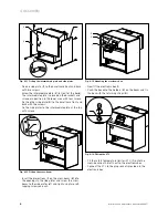
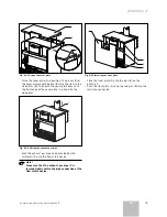
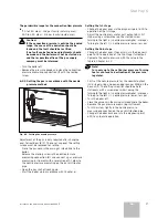
Fig. 4.11 Fitting the intermediate plate and side plates
• Fix one side plate (
1
) to the baseframe front and back
with two screws.
• Screw the intermediate plate (
2
) in front of the boiler.
The intermediate plate is placed on the brackets and
screwed in position in the lower area with four screws.
• Fix the other side plate (
3
) to the baseframe front and
back with two screws.
• Fix the side plates to the intermediate plate at the top
with screws.
2
1
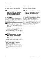
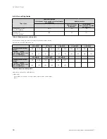
Fig. 4.12 Fitting the cross-beam
• Insert the projections (
1
) on the cross-beam (
2
) into
the openings in the side plates and screw the cross-
beam to the side plates left and right using two self-
tapping screws on each.
1
2
3
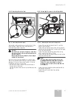
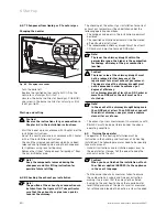
Fig. 4.13 Mounting the electronic box
• Now fit the electronic box (
1
).
• Push the box onto the holders (
2
) on the beam and fix
the box with the retaining straps (
3
).
1
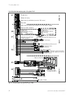
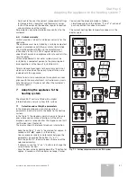
Fig. 4.14 Fitting the STL
• Fit the safety temperature limiter (STL) (
1
) onto the
cross-beam on the left next to the electronic box.
• Connect the STL to the plug sockets provided in the
electronic box.
4 Assembly
Содержание atmocraft
Страница 1: ...VK 654 9 1654 9 atmoCRAFT DE AT GB...
Страница 2: ......
Страница 44: ...835553_02 DEATGB 092006...

