


2GM
2-3-21
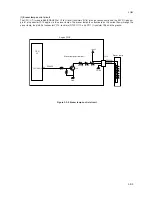
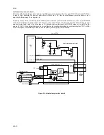
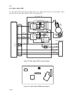
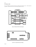
(1) Interlock switch
The interlock switch is located on the high voltage PWB and opened and closed in conjunction with the front cover or the
front top cover via the interlock lever. This switch connects and disconnects the +24 V DC power supply line. If the front
cover or the front top cover is open, the interlock switch is open, and the +24 V DC to the high voltage output circuit, bias
PWB, engine PWB, and the power supply PWB is disconnected, deactivating the high voltage output, laser output, main
motor output for safety. The cooling fan is an exception: Since the cooling fan is directly fed with +24 V DC from the power
supply unit at the primary side (+24V1) of the interlock switch, the cooling fan is not deactivated even the cover is open.
Front cover
High voltage PWB
Power supply unit
Interlock
switch
Interlock lever
Projection
Projection
Front top cover
Machine left side view
+24V1
+24V1
+24V2
+24 V DC
output
+24V2
+24V2
+24V2
High voltage
output circuit
Engine PWB,
Bias PWB,
etc.
Cooling fan
Triac, etc.
Figure 2-3-15 Interlock switch
Содержание CD 1018
Страница 1: ...Service Manual MFP Copy CD 1018 Date 17 03 2005 ...
Страница 2: ...Service Manual MFP Copy DC 2018 Date 17 03 2005 ...
Страница 70: ...2GM 1 5 2 2 Paper misfeed detection conditions Registration sensor Exit sensor Figure 1 5 2 ...
Страница 110: ...2GM 1 6 17 15 Remove four screws 16 Remove the drive unit Figure 1 6 20 Removing the drive unit Screws Drive unit ...
Страница 124: ...2GM 1 6 31 Eraser lamp 9 Remove the eraser lamp Figure 1 6 35 Removing the eraser lamp ...


