


2GM
2-3-13
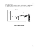
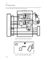
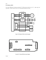
(3) Polygon motor control circuit
The main controller PWB supplies the 2598.4 Hz clock pulse (PLGCLK) via the engine PWB to the PLL control IC (IC1) for
the polygon motor. To begin printing, the engine CPU U1 turns PLGDR to H level, the PLL control IC (IC1) starts to revolve
the polygon motor so that the revolution is 25,984 rpm which depends on the PLGCLK clock pulse. When PLL control IC
(IC1) finds that the polygon motor is revolving at the rated speed, turns PLGDRN to L level to acknowledge the engine CPU
that the rated speed has been achieved.
On the contrary, if PLGRDYN does not turn to L level within 8 seconds since PLGDRN has been L level.
Figure 2-3-8 Polygon motor control circuit
GND
2
2
3
3
1
1
Q16
Q17
+5V
3.3V
R32
+
PGND
PGND
+24V3
+24V3
PGND
PLGDRN
PLGRDYN
PLGCLK
YC13
5
4
3
2
1
PLGRDYN
PLGCLK
PLGDR
CPU
U1
Polygon motor
PLL
control IC
(IC1)
2598.4 Hz
25,984 rpm
Engine PWB
Main PWB
Polygon motor control circuit
Laser scanner unit
Содержание CD 1018
Страница 1: ...Service Manual MFP Copy CD 1018 Date 17 03 2005 ...
Страница 2: ...Service Manual MFP Copy DC 2018 Date 17 03 2005 ...
Страница 70: ...2GM 1 5 2 2 Paper misfeed detection conditions Registration sensor Exit sensor Figure 1 5 2 ...
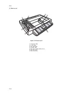
Страница 110: ...2GM 1 6 17 15 Remove four screws 16 Remove the drive unit Figure 1 6 20 Removing the drive unit Screws Drive unit ...
Страница 124: ...2GM 1 6 31 Eraser lamp 9 Remove the eraser lamp Figure 1 6 35 Removing the eraser lamp ...


