


2GM
2-1-6
7
8
6
1
2
4
3
5
Original
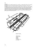
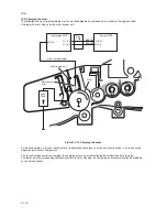
Figure 2-1-6 ISU unit
1
Exposure lamp
2
Scanner reflector
3
Mirror A
4
Mirror A
5
Mirror B
6
ISU lens
7
CCD image sensor
8
CCD PWB
(1) ISU unit
The ISU unit consists of an exposure lamp, three mirrors, an ISU lens, a CCD PWB, and so on. Also an inverter PWB for
driving the exposure lamp and a scanner home position sensor for detecting the home position of the ISU unit are
incorporated.
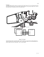
The original on the contact glass is exposed to the light of the exposure lamp that is reflected by the reflector. The image
is input through reflection by the three mirrors and through the ISU lens to the CCD image sensor on the CCD PWB. The
CCD image sensor scans one row of the image in the main scan direction, converts it to electric signals, and outputs
them to the main PWB. Then the ISU unit is moved in the sub scan direction along the scanner shaft, and the CCD
image sensor scans the next row of the image in the main scan direction. The operation described above is repeated for
scanning the overall image of the original. If an optional DP is used, the ISU unit stops at the position of the DP contact
glass and scans sequentially one row of the image on the original in synchronization with the moving timing of the
original in the sub scan direction by driving the DP.
Содержание CD 1018
Страница 1: ...Service Manual MFP Copy CD 1018 Date 17 03 2005 ...
Страница 2: ...Service Manual MFP Copy DC 2018 Date 17 03 2005 ...
Страница 70: ...2GM 1 5 2 2 Paper misfeed detection conditions Registration sensor Exit sensor Figure 1 5 2 ...
Страница 110: ...2GM 1 6 17 15 Remove four screws 16 Remove the drive unit Figure 1 6 20 Removing the drive unit Screws Drive unit ...
Страница 124: ...2GM 1 6 31 Eraser lamp 9 Remove the eraser lamp Figure 1 6 35 Removing the eraser lamp ...


