ACCESSORIES
Section
6-10
•
If there is a button head screw located on the top of the Dual Head and or the single head, remove it.
2.0
2.0
L
R
DUAL HEAD
Beam Tube
•
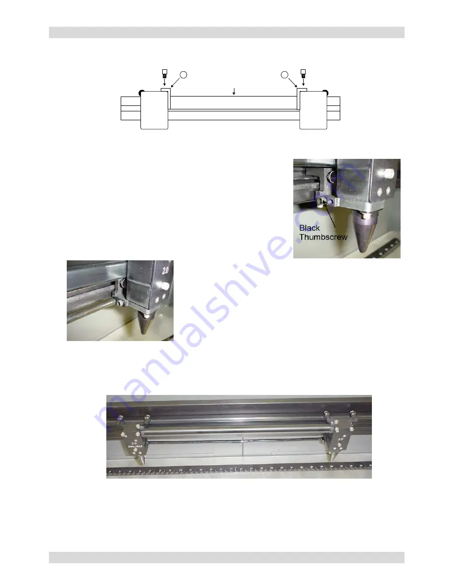
Pick up the Dual Head tube and note the “L” (Left) and “R” (Right) markings. Install the tube using
the supplied thumbscrews and tighten securely.
•
If you have the Air Assist option, locate the 1 (one) black
thumbscrew on the side of the Single Head. This thumbscrew
serves two purposes, it blocks air from coming out when in Single
Head operation and secures the Dual Head Air Hose when in Dual
Head operation. Regardless of whether or not you will be using
the Air Assist option, you should always attach the Air Hose to get
it out of the way.
REMINDER: If you have the Air Assist option
and will not be using it, you MUST remove the air assist
cone(s) before operating the system otherwise damage to the
Focus Lens will occur. Refer to your Air Assist
documentation on how to remove the cone(s) properly
.
•
Remove the thumbscrew and attach the end of the air hose to
the single head by inserting the brass tube into the hole where
the thumbscrew was removed. Attach the thumbscrew into the
other threaded hole (right next to the original hole), and tighten
securely.
•
Installation is now complete. Turn the laser system ON and observe the control panel display. Above
the “Initializing” statement you should see “(DH)” next to the model name indicating that you are now
in “Dual Head” mode.
•
Press the “X-Y” button to illuminate the Red Diode Pointer. You will notice that the Single Heads red
dot will be brighter than the Dual Head’s red dot. This is because the Beam Splitter, inside the Dual
Head does not reflect/pass visible light at a 50/50 ratio. Using the Motion Controls, position the Dual
Head all the way as far as it will go into the upper left corner of the engraving area (0,0). It should be
relatively close to (0,0) with +/- 1/16
th
of an inch. Now observe the position of the Single Head red
dot
.
This is the (0,0) position of the second object and your reference point for placing your material.
Содержание SuperSpeed-660
Страница 6: ......
Страница 20: ...INSTALLATION Section 2 8...
Страница 34: ...SYSTEM OPERATION Section 3 14...
Страница 44: ...BASIC MAINTENANCE Section 4 10...
Страница 68: ...MATERIAL SETTINGS GUIDE Section 5 24...


