UNITED FIRE SYSTEMS
STANDPIPE-
PAC™ MODEL SSS-101
DESIGN, INSTALLATION, OPERATION, AND MAINTENANCE MANUAL
REVISION 2.00
P/N 10-540101-001
Page 19
STEP-BY-STEP GUIDE, CONTINUED
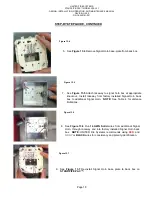
10. See
Figures 13.7
,
13.8
and
Figure 12 Wiring Diagram
. Strip ends of wire
installed in Step 8. Attach wires removed in Step 5 and wires installed in
Step 8 to Signal Horn base plate terminals.
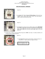
11. See
Figure 13.9
. Connect wires at additional Signal Horns.
IMPORTANT!
Do not branch Signal Horn circuit. Run circuit from the first Signal Horn
to the second Signal Horn, then the second Signal Horn to the third,
and so on.
12. Repeat steps 5 through 10 for each additional Signal Horn.
NOTE
: See Table 4 for distance limitations and
maximum number of additional devices.
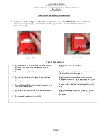
13 See
Figure 13.10
. Install end of line resistor, retained from Step 5, at
last Signal Horn, between positive and negative terminals.
End-of-Line Resistor on last
device on Signal Horn circuit
En
Figure 13.8
En
Figure 13.9
En
Figure 13.10
Содержание STANDPIPE-PAC SSS-101
Страница 2: ...THIS SURFACE DELIBERATELY LEFT BLANK...
Страница 55: ...THIS SURFACE DELIBERATELY LEFT BLANK...
Страница 65: ...THIS SURFACE DELIBERATELY LEFT BLANK...
Страница 66: ...THIS SURFACE DELIBERATELY LEFT BLANK...


