UNITED FIRE SYSTEMS
STANDPIPE-
PAC™ MODEL SSS-101
DESIGN, INSTALLATION, OPERATION, AND MAINTENANCE MANUAL
REVISION 2.00
P/N 10-540101-001
Page 20
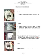
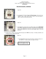
STEP-BY-STEP GUIDE, CONTINUED
Do
make sure the Signal Horn covers are clicked firmly into
place onto the Signal Horn base plates once wiring is
complete.
×
Don’t
wire 115 VAC on this circuit.
Do
use a minimum of 14 AWG size wire.
×
Don’t
mix up the polarity. Know the polarity at both ends of
the wiring. Wire per polarity diagram.
Do
wire additional devices per Figure 12. The end-of-line
resistor must be moved to the last device in the circuit per
Figure B.
×
Don’t
exceed the current capacity of the circuit when
adding additional horns to the
STANDPIPE-
PAC™
. Each
additional horn adjusted to FULL VOLUME draws 0.047
amps. As noted on page 1, the current for all external
devices, including the factory-installed signal horn, is 1.0
amp.
×
Don’t
branch the signaling circuit. Wire horns in parallel,
from one horn to the next. See
Figure 12: Wiring
Diagram.
Do
use
RED
and
GRAY
wire for (+) and (-) conductors so it
is easy to maintain polarity.
Do
install the end-of-line resistor on the terminals indicated.
Do
ensure additional device(s) are 12VDC.
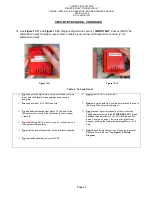
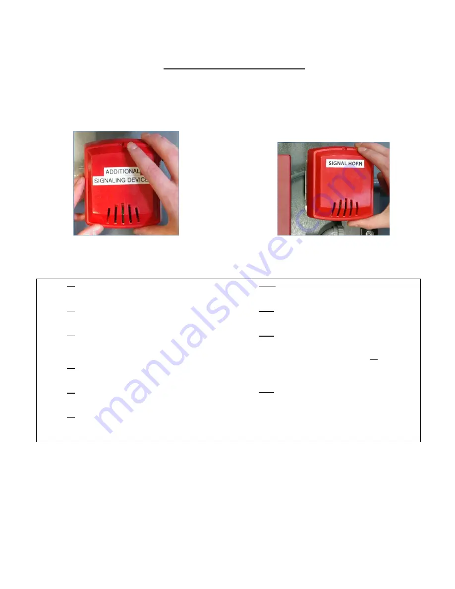
14. See
Figure 13.11
and
Figure 13.12
. Replace Signal Horn cover(s).
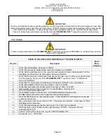
IMPORTANT
: Cover(s) MUST be
fastened correctly for proper wire contact. Trouble signal will occur if Signal Horn cover(s) is not
fastened correctly.
Table 5 - Do’s and Don’ts
En
Figure 13.11
En
Figure 13.12
Содержание STANDPIPE-PAC SSS-101
Страница 2: ...THIS SURFACE DELIBERATELY LEFT BLANK...
Страница 55: ...THIS SURFACE DELIBERATELY LEFT BLANK...
Страница 65: ...THIS SURFACE DELIBERATELY LEFT BLANK...
Страница 66: ...THIS SURFACE DELIBERATELY LEFT BLANK...


