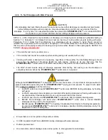
UNITED FIRE SYSTEMS
STANDPIPE-
PAC™ MODEL SSS-101
DESIGN, INSTALLATION, OPERATION, AND MAINTENANCE MANUAL
REVISION 2.00
P/N 10-540101-001
Page 23
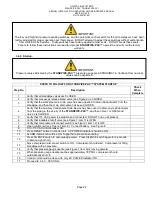
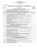
3.4.3. Testing
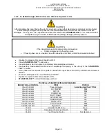
STEPS TO FOLLOW FOR STANDPIPE-
PAC™ SYSTEM TESTING
Step No.
Description
Check
When
Complete
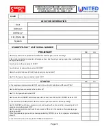
### VERIFICATIONS BEFORE TESTING ###
1
If control unit dialer is connected to telephone lines, ensure that party receiving signals is
aware that testing activities are occurring.
2
Verify that pressure gauge (see Figure 1 item 5) indicates approximately 18 PSIG.
3
Verify that control unit AC POWER indicator is ON and no other indicators are lit.
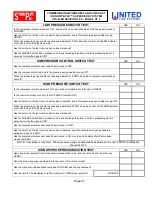
### LOW-LIMIT PRESSURE-SENSING SWITCH and AUTOMATIC AIR COMPRESSOR CONTROL SWITCH TEST
###
4
Verify that compressor disconnect switch (see Figure 1 item 12) is OFF.
5
Move lockable shutoff valve (see Figure 1 item 7) to CLOSED position.
6
Press and hold button on Test / Service Device (see Figure 1 item 13). Verify that pressure
gauge needle is moving DOWN.
7
When pressure gauge needle reaches approximately 7 PSIG, control unit ALARM indicator
should be ON. Signal horn (see Figure 1 item 9) should sound.
8
Release button on Test / Service Device.
9
Press SILENCE switch to acknowledge alarm. Press SILENCE switch again for 2 seconds
to silence signal horn.
10
Move compressor disconnect switch to ON. Compressor should start. Pressure gauge
needle should move UP.
11
When pressure gauge needle moves above approximately 7 PSIG, control unit should clear
and ALARM indicator should be OFF.
12
When pressure gauge needle reaches approximately 18 PSIG, compressor should
automatically shut off.
### HIGH-LIMIT PRESSURE-SENSING SWITCH TEST ###
13
Verify that compressor disconnect switch is ON.
14
Verify that lockable shutoff valve is in CLOSED position.
15
Verify that control unit AC POWER indicator is ON and no other indicators are lit.
16
Press and hold button on Test / Service Device. Verify that pressure gauge needle is moving
UP.
17
When pressure gauge needle reaches approximately 23 PSIG, control unit ALARM indicator
should be ON. Signal horn should sound.
18
Release button on Test / Service Device.
19
Press SILENCE switch to acknowledge alarm. Press SILENCE switch again for 2 seconds
to silence signal horn.
20
Move compressor disconnect switch to OFF.
21
Press and release button on Test / Service Device until pressure gauge reads between 13
and 18 PSIG. Control unit ALARM indicator should be OFF. Signal horn should be OFF.
22
Move compressor disconnect switch to ON.
23
Move lockable shutoff valve to OPEN position.
24
Pressure gauge may drop. Compressor may start. Pressure gauge should stabilize
between 13 and 18 PSIG, and compressor should then be OFF.
### STANDPIPE DEPRESSURIZATION TEST ###
25
Remove cap from manual air release bleed valve. Open manual air release bleed valve all
the way OPEN.
26
Pressure gauge reading should drop to 0 (zero) PSIG in approximately 3 minutes.
27
Close manual air release bleed valve.
28
Pressure gauge reading should be approximately 13 PSIG (or more) in the design amount of
time (see Section 2
– DESIGN).
29
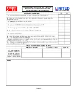
Proceed to 3.4.4
– PLACING IN SERVICE.
Содержание STANDPIPE-PAC SSS-101
Страница 2: ...THIS SURFACE DELIBERATELY LEFT BLANK...
Страница 55: ...THIS SURFACE DELIBERATELY LEFT BLANK...
Страница 65: ...THIS SURFACE DELIBERATELY LEFT BLANK...
Страница 66: ...THIS SURFACE DELIBERATELY LEFT BLANK...


