UNITED FIRE SYSTEMS
STANDPIPE-
PAC™ MODEL SSS-101
DESIGN, INSTALLATION, OPERATION, AND MAINTENANCE MANUAL
REVISION 2.00
P/N 10-540101-001
Page 17
STEP-BY-STEP GUIDE TO INSTALLING ADDITIONAL SIGNAL HORNS TO STANDPIPE-
PAC™
1. Ensure that the
STANDPIPE-
PAC™
control unit has
NOT
been powered up, with AC power and batteries
disconnected.
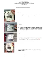
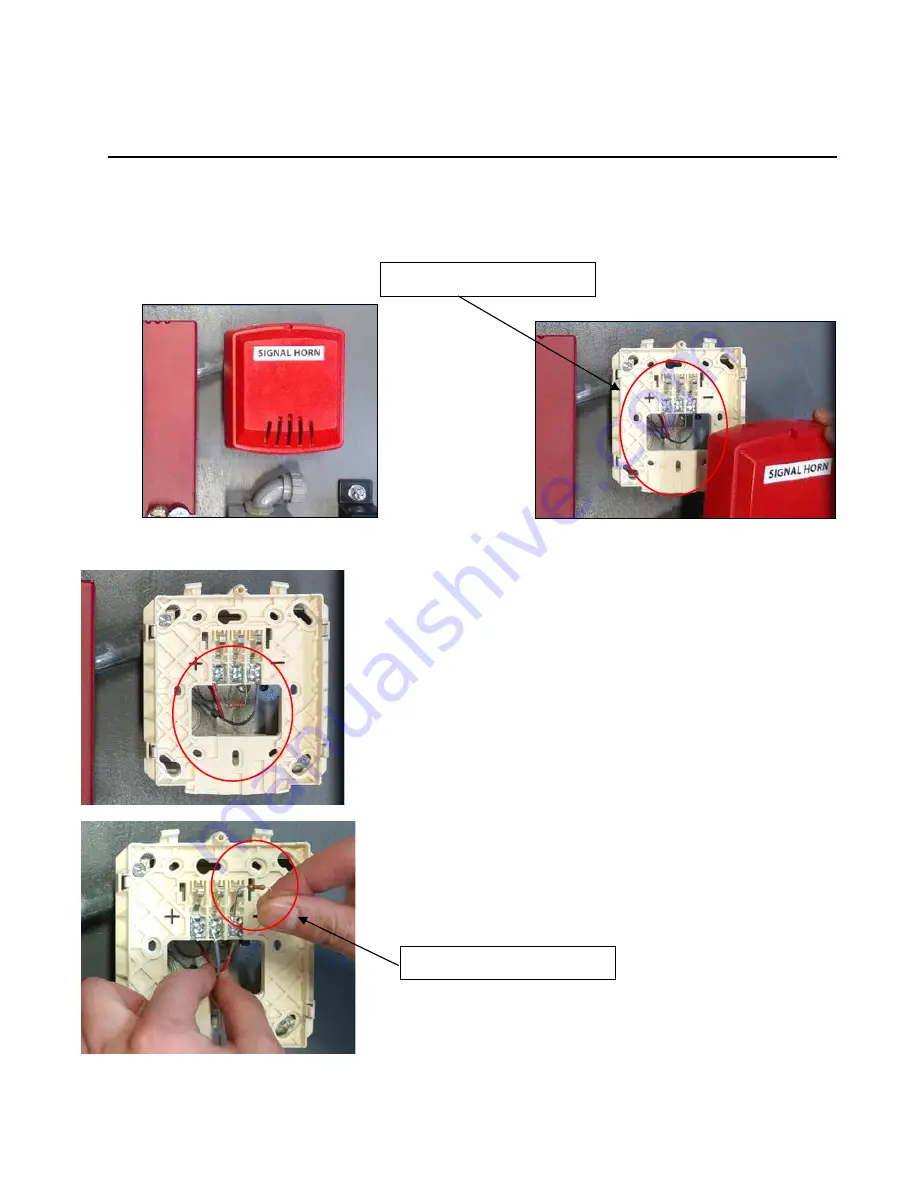
2. See
Figure 13
and
Figure 13.1
. Remove Signal Horn cover from factory installed Signal Horn assembly on
STANDPIPE-
PAC™.
En
End-of-Line Resistor
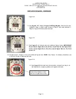
3. See
Figure 13.2
. Visually inspect Signal Horn base-plate connections.
Locate positive and negative terminals on base-plate.
NOTE
:
RED
wire connects to positive terminal;
GRAY
wire connects to negative
terminal.
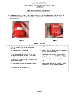
4. See
Figure 13.2
Locate
end-of-line resistor
; factory installed
between positive and negative terminals on Signal Horn base-plate.
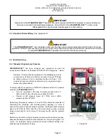
5. See
Figure 13.3
Disconnect
RED
and
GRAY
wires and remove end-
of line resistor from base plate.
IMPORTANT:
DO NOT DISCARD
END OF LINE RESISTOR
En
End-of-Line Resistor
En
Figure 13
En
Figure 13.1
En
Figure 13.2
En
Figure 13.3
Содержание STANDPIPE-PAC SSS-101
Страница 2: ...THIS SURFACE DELIBERATELY LEFT BLANK...
Страница 55: ...THIS SURFACE DELIBERATELY LEFT BLANK...
Страница 65: ...THIS SURFACE DELIBERATELY LEFT BLANK...
Страница 66: ...THIS SURFACE DELIBERATELY LEFT BLANK...


