background image

12

3


SETTING PROCEDURE

12

SETTING PROCEDURE

Chapter

3

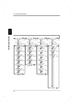
Setting Mode 6

[    ]

[

]

[

]

[

]

[

]

(P44)

(P44)

(P44)

(P44)

(P44)

(P44)

(P44)

設定

Ãß›³ºÆ›7

[    ]

[

]

[

]

[

]

[

]

(P45)

(P45)

(P45)

(P45)

(P45)

Setting Mode 8

Tare Reset

Digital Zero

(P23)

Setting Mode 9

[    ]

[    ]

[

]

[

]

[

]

[

]

[

]

[

]

[

]

[

]

(P23)

(P24)

(P24)

(P42)

(P42)

(P43)

(P21)

(P21)

(P22)

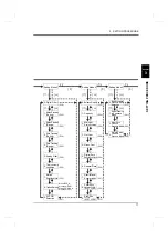
Setting Mode 7

Password

0:

1:

2:

3:

9:

Digital Zero

Reset

External

Control Output

0:

Selection 0

External

Control Output

1:

Selection 1

External

Control Output

2:

Selection 2

External

Control Output

3:

Selection 3

External

Control Output

4:

Selection 4

External

Control Output

5:

Selection 5

External

Control Output

6:

Selection 6

External

Control Input

0:

Selection 0

External

Control Input

1:

Selection 1

External

Control Input

2:

Selection 2

External

Control Input

3:

Selection 3

External

Control Input

4:

Selection 4

0:

Zero

Calibration

1:

Actual Load

Calibration

0:

Tare

Subtraction

4: Sequence

Start

5: Sequence

Stop

6:

Sequence

Error Reset

2: Equivalent

Calibration

Содержание F160

Страница 1: ...01AUG2017REV 1 06 WEIGHING CONTROLLER F160 CC Link Ver 1 10 OPERATION MANUAL...

Страница 2: ...stallation maintenance and inspection of the F160 should be performed by personnel having technical knowledge of electricity In order to have an F160 weighing controller used safely notes we would lik...

Страница 3: ...ll the attached terminal block cover after wiring to the power input terminals Otherwise electric shocks may result Before applying power carefully check the wiring etc Use at a proper power supply vo...

Страница 4: ...method its protective performance may be impaired Maintenance When performing maintenance disconnect the power Do not wipe with a wet rag or with benzine thinner alcohol etc Doing so may cause discol...

Страница 5: ...ances with regard to adverse effects on the environment and human body What is RoHS It is an abbreviation for Restriction on Hazardous Substances which is implemented by the European Union EU The Dire...

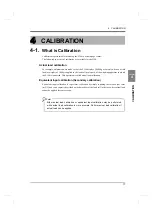
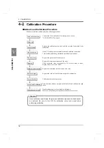
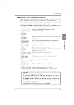
Страница 6: ...ocedure 13 Setting Method 13 4 CALIBRATION 17 4 1 What is Calibration 17 4 2 Calibration Procedure 18 Actual Load Calibration Procedure 18 Equivalent Input Calibration Procedure 19 4 3 Actual Load Cal...

Страница 7: ...ower Limit Near Zero Setting Code 06 to 08 35 Over Under Comparison Upper Lower Limit Comparison Near Zero Comparison Setting Code 20 to 22 35 Over Under Comparison Mode Setting Code 27 35 Upper Lower...

Страница 8: ...Memory Assignments 55 Setting Procedures 63 Sample Ladder 65 8 SPECIFICATIONS 70 8 1 Specifications 70 Analog Section 70 Setting Section 70 Display Section 71 External Input Output 71 Interface 71 Ge...

Страница 9: ...CONTENTS VIII CONTENTS VIII M E M O...

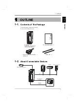
Страница 10: ...ontains the following Be sure to check them before use 1 2 About Connectable Devices 1 OUTLINE 01NOV2007REV 1 00 WEIGHING CONTROLLER F160 F160 body 1 F160 operation manual 1 External input output conn...

Страница 11: ...function Go to a setting item selection state The last item number is selected Select the previous item number Increment the numerical value by one No function Go to a setting item selection state Th...

Страница 12: ...ll s The adaptable plug is Osada manufactured ETB42 07P or equivalent Connector optional type CN80 5 SI F terminal 2 wire serial interface is to connect UNIPULSE peripheral equipment such as printer r...

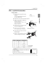
Страница 13: ...m with the screws Red screw Black screw 5 Install the terminal block cover and fix it with the screws two WARNING Be aware that the voltage drops depending on the wire thickness and length Never input...

Страница 14: ...not to let the tip spread out 5 Tighten the screw with the screwdriver 0 5Nm of tightening torque is recommended 6 Lightly pull the wire to make sure that it is securely clamped 7 Insert the wire con...

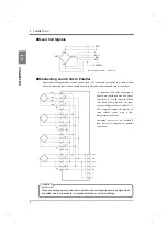
Страница 15: ...SIG EXC EXC SIG EXC SIG F G S S n number load cells connected in parallel are considered one unit whose capacity is n x rated capacity of load cells load cells must have the same capacity bridge resi...

Страница 16: ...ectly CAUTION The load cell excitation voltage of the F160 is 10V Unless its maximum excitation voltage is 10V or more the load cell may generate heat or be damaged For connecting a 4 wire load cell t...

Страница 17: ...ans of a transistor open collector COM push toggle 5V TTL open collecter F160 IN IN Approx inside transistor Use external elements which withstand Ic 10mA Leakage of external elements must be within 3...

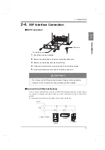
Страница 18: ...the screws two Connection of External Devices This is a 2 wire serial interface to connect a UNIPULSE manufactured printer external display etc which is a nonpolar type and to which up to three exter...

Страница 19: ...Compensation Feed Discharge Control Mode Near Zero Comparison Over Under Comparison Mode U L Limit Comparison Mode P36 P36 P36 P41 P43 P43 P37 P37 P37 P35 P35 P35 P33 P24 P37 P37 P35 P36 P33 0 1 2 3...

Страница 20: ...d Motion Detection Range Option Setting Digital Filter Analog Filter P26 P25 Motion Detection Mode 0 1 2 3 5 7 8 9 Zero Tracking Period 0 1 3 4 6 7 Gravitational Acceleration 4 Zero Tracking Range SI...

Страница 21: ...election 1 External Control Output 2 Selection 2 External Control Output 3 Selection 3 External Control Output 4 Selection 4 External Control Output 5 Selection 5 External Control Output 6 Selection 6...

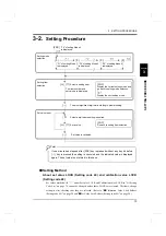
Страница 22: ...layed Select a setting item The most significant digit starts blinking to prompt setting Select a digit where setting is desired Set Value is validated F0 of setting Mode 0 Setting item Set value inpu...

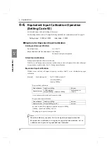
Страница 23: ...4 Determine it with To cancel the set value change press FNC without pressing to go back to the set value display Example 2 Setting method by numerical value Setting Balance Weight to 25000 1 From th...

Страница 24: ...Example 4 Setting method for command execution As for operational commands setting codes 91 and 92 in 9 1 Setting Code List on page 78 operation is executed when a set value is input and then determi...

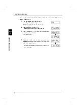
Страница 25: ...een set setting mode 9 by pressing FNC 2 Select item number 2 with The item number and set value are displayed 3 Enable change with so that the most significant digit of the set value flashes Set 1 wi...

Страница 26: ...weighing apparatus to which the F160 is connected This operation is called actual load calibration Equivalent input calibration Secondary calibration Equivalent input calibration is to perform calibr...

Страница 27: ...d by 10 scale divisions or more display shows over scale OFL2 Register the minimum scale division of the scale Register the value of load balance weight for calibration Calibration the initial zero po...

Страница 28: ...ecimal point Register the maximum capacity of the scale If the registered value is exceeded by 10 scale divisions or more display shows over scale OFL2 Register the minimum scale division of the scale...

Страница 29: ...le OFL2 Setting range 00000 to 99999 Initial value 10000 Minimum Scale Division Setting code 42 Set the minimum unit for weighing scale division The value of capacity minimum scale division is the res...

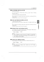
Страница 30: ...ror is displayed take measures according to the error message and do zero calibration again For details of each error refer to 9 2 Error List on page 85 Calibration Value Lock Setting code 48 Upon com...

Страница 31: ...ration Equivalent input calibration Whether or not the load cell output at capacity is within 2mV V is not checked during span calibration Example Scale making with 3mV V 3000kg load cell initial tare...

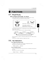
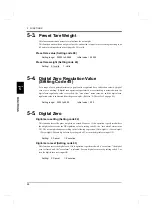
Страница 32: ...ayed for a while to indicate the current weight value After execution of calibration operation gross weight display is forced 5 2 Tare Subtraction Tare subtraction Setting code 80 This function zeros...

Страница 33: ...ro alarm status turns on and the digital zero regulation value is subtracted from the gross weight Refer to 9 2 Error List on page 85 Setting range 0000 to 9999 Initial value 200 5 5 Digital Zero Digi...

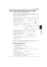
Страница 34: ...ersion is made and if at least one of them exceeds the range the STABLE signal turns OFF immediately D1 is the difference between the current weight value and 0 09 sec old weight value When the Stab i...

Страница 35: ...cking is the function to reset gross weight to zero automatically when the state remaining the zero point drift within the zero tracking range continues more than set period Zero tracking period must...

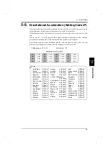
Страница 36: ...on 01 9 806 02 9 805 03 9 804 04 9 803 05 9 802 06 9 801 07 9 800 08 9 799 09 9 798 10 9 797 11 9 796 12 9 795 13 9 794 14 9 793 15 9 792 16 9 791 Point Amsterdam 9 813m s2 Athens 9 800m s2 Auckland N...

Страница 37: ...his is a low pass filter to eliminate noise components from input signals from the load cell and also stabilize the weight value by averaging Select the cutoff frequency from 2Hz 4Hz 6Hz and 8Hz By lo...

Страница 38: ...materials are to be fed from the material tank to the weighing tank At first the feeding valves are to be fully opened to feed and closed in the order of SP1 SP2 and SP2 SP3 at the time of Final Set P...

Страница 39: ...gnal or under signal turns ON 6 Raw materials are discharged from the weighing tank to a container The valves of the weighing tank should be opened Completion of discharge is confirmed with the Near Z...

Страница 40: ...the weighing tank with raw materials from the material tank to weigh 1 The valves of the material tank are opened by the lower limit signal and raw materials are fed into the weighing tank 2 It is det...

Страница 41: ...case when comparing Upper Lower limit comparison and Near Zero comparison with Gross weight Final and Over Under with Net weight The feeding valves and discharge valves should be opened and closed th...

Страница 42: ...d 1 Display without inverting the sign Simple Comparison Control and Sequence Control Simple comparison control Compares weight value with discharging value regulerly Output is always ON when the weig...

Страница 43: ...Weight value Final Set point 1 SP2 Weight value Final Set point 2 SP3 Weight value Final Compensation Over Weight value Final Over Go Final Over Weight value Final Under Under Weight value Final Under...

Страница 44: ...ode No 21 Select the weight value for upper lower limit comparison Setting 0 Gross weight 1 Net weight 2 Comparison OFF 3 Near zero comparison Code No 22 Select the weight value for near zero comparis...

Страница 45: ...al vibrations caused by opening and closing of valves Complete output time Set the length of the complete signal complete relay to be output when weighing is completed Setting range and code No of eac...

Страница 46: ...lation Setting Code 25 17 to 19 The auto free fall compensation function automatically corrects variations in free fall which is a great factor of weight alarms for accurate weighing Here set the para...

Страница 47: ...Set a coefficient of 1 or less for multiplication to prevent variations in compensation value Times Actual weighing Error Average count of AFFC CPS 0 0 Power ON 1 20 050 0 050 1 0 500 2 20 040 0 040...

Страница 48: ...Lower limit comparisons are always made deregarding the setting of the Upper Lower limit comparison mode of setting code 28 t1 Comparison inhibit time comparison inhibit time of setting code 10 t2 Ju...

Страница 49: ...2 SP3 output signal and over go under judgment signal comparing weight value from gross weight net weight with setting code 20 Near zero confirmation at the sequence mode Setting code 52 Setting for c...

Страница 50: ...limit comparison mode of setting code 28 t1 Comparison inhibit time comparison inhibit time of setting code 10 t2 Judging time judging time of setting code 11 t3 Complete output time complete output t...

Страница 51: ...de 84 85 When the stop signal turns ON during weight cycle a sequence error 2 will result and all the signals of SP1 SP2 and SP3 are turned OFF If the start signal is turned ON when the stop signal is...

Страница 52: ...r of judging times in the sequence mode When the number of auto zero times is set at zero the auto zero at start time becomes invalid When the number of judging times is set at zero the sequence becom...

Страница 53: ...e same signal becomes valid Connector Pin Assignments Output assignments Output allocation Pin No Port Setting code Initially specified signal 1 COM External power GND 2 External control output 0 60 0...

Страница 54: ...nput Meanings of Signals Digital zero reset Edge input Resets the zero point correction value by digital zero at the ON edge and also cancels the zero alarm if it has occurred Digital zero Edge input...

Страница 55: ...f hold input operation will result on OR condition with the RY0014 signal Feed Discharge Level input Valid only in setting code 23 feed discharge control mode is set at 2 external selection external c...

Страница 56: ...e display and printer Each display and printer can select the data individually About the auto print command The F160 can output the auto print command to the printer or display connected to the SI F...

Страница 57: ...anufactured by FUJITSU COMPONENT or equivalent Connector cover FCN 360C032 B manufactured by FUJITSU COMPONENT or equivalent Connector Cover optional type CN51 No Signal No Signal A1 COM B1 COM A2 OUT...

Страница 58: ...weight 2 Tare weight 3 Ext BCD output rate Setting 0 10 1 20 2 50 3 100 4 200 5 500 6 1000 Times sec BCD output data form When the BCD option is mounted you can select the output data form from BCD a...

Страница 59: ...Output Data Selection is External selection Logic Switching Switch the logic of output signals with pin B14 When COM and pin B14 are open negative logic When they are short circuited positive logic A1...

Страница 60: ...g as the BCD Data Hold signal is inputted data can be read reliably but because the data is not renewed it may be different from proper data Equivalent Circuit Output The signal output circuit is oper...

Страница 61: ...cording to the output data B11 Gross weight OFL3 Net weight OFL1 Refer to 9 2Error List on page 85 Tare weight Tare weight 99999 STROBE Strobe pulses are outputted in synchronization with BCD data dut...

Страница 62: ...remote device occupying two stations In the case of construction with the F160 alone up to 32 units including one master can be connected to the bus Commands and parameters can be set on the CC Link T...

Страница 63: ...erate the lever as the plug is connected otherwise the board may be damaged How to connect When the DA and DB signal lines and resistance are to be connected to the connector be aware that poor contac...

Страница 64: ...the application program of the PLC the buffer memory is accessed by the FROM TO instruction at A series The following explanations are given on the F160 of station No 1 Buffer Memory Assignments Data...

Страница 65: ...the controller For details refer to 9 2 Error List on page 85 Error assistance code 4bit BCD 0 to 9 Indicates the error assistance code of the controller For details refer to 9 2 Error List on page 85...

Страница 66: ...0 to 99 Auto Free Fall Compensation Coefficient 17 0 to 3 Average Count of Auto Free Fall Compensation 18 1 to 9 Auto Free Fall Compensation Regulation 19 0 to 99999 Over Under Comparison 20 0 to 2 Up...

Страница 67: ...ection 2 62 0 to 16 External Control Output Selection 3 63 0 to 16 External Control Output Selection 4 64 0 to 16 External Control Output Selection 5 65 0 to 16 External Control Output Selection 6 66...

Страница 68: ...Fall Compensation Coefficient 17 External Control Output Selection 2 62 Average Count of Auto Free Fall Compensation 18 External Control Output Selection 3 63 Auto Free Fall Compensation Regulation 19...

Страница 69: ...Zero RY0011 Digital Zero Reset RY0012 Tare Subtraction RY0013 Tare Reset RY0014 Hold RY0015 RY0016 RY0017 RY0018 Sequence Start RY0019 Sequence Stop RY001A Sequence Error Reset RY001B Zero Calibratio...

Страница 70: ...put Tare Reset Cancels tare subtraction at the edge input Digital Zero Zeros the gross weight at the edge input Digital Zero Reset Cancels digital zero at the edge input Hold Holds the weight value at...

Страница 71: ...ace 1 RX000A RX000B RX000C RX000D RX000E RX000F 00E1H RX0010 Near Zero RX0011 SP1 RX0012 SP2 RX0013 SP3 RX0014 Over RX0015 Go RX0016 Under RX0017 Stable RX0018 Complete RX0019 Over Scale RX001A Hold R...

Страница 72: ...weight value final compensation set value Over Turns ON when the weight value final over set value Go Turns ON when the weight value is neither over nor under Under Turns ON when the weight value fina...

Страница 73: ...tion edge input Pulse width should be ON more than 20ms Reading out of set value timing To read set values turn the R W ON Read the reading data area after making sure that the response has turned ON...

Страница 74: ...d if they correspond the value is incremented which is repeated up to 99999 0 follows after 99999 Flow Initial setting D300 99999 Substitute 0 into D300 Write the value of D300 to the final after maki...

Страница 75: ...K1 D0 K0 D3 H0 H0 H0 H0 H0 H0 H0 H0 D4 H1201 D12 RST SET PLS MOV MOV MOV H1 MOV H6 MOV MOV MOV MOV MOV MOV MOV MOV H10 MOV H20 H2 H2 H2 H2 TO TO TO TO 1 device connected X20 X2F M0 M1 M1 M9038 X20 X2...

Страница 76: ...est ON WOR WAND Final command RWr PLC read value from F160 M9036 125 135 M100 M101 RST SET Up to here initial setting for communication H0E0 H2 FROM RX PLC read value from F160 H2 FROM Copy response t...

Страница 77: ...sponse goes ON MOV Request OFF WAND Y2 M9038 M101 254 M106 M106 SET RST M106 331 M101 When response turns ON WAND H4 D208 H160 TO H2 To M103 When response goes OFF Final command Request ON H2 TO D303...

Страница 78: ...69 7 OPTION Setting Code 38 69 OPTION Chapter 7 M100 M101 M102 M103 M104 M106 D300 H4 END SET RST RST RST RST RST K0 K0 DMOV H160 M9038 H2 TO Initialization 392 416...

Страница 79: ...V RTI Gain drift Within 15ppm Analog filter Bessel low pass filter 12dB oct cutoff frequency 2 4 6 8Hz A D converter Rate 1000times sec Resolution 24bit Minimum indication resolution 1 10000 Secondary...

Страница 80: ...Limit Stable Weight Alarm Sequence Error Final Error In Operation RUN Clock in an approximately one second cycles Interface Standard equipment SI F 2 wire serial interface This is a simple output ser...

Страница 81: ...D mm excluding projections Operating conditions Temperature Operating temperature range 10 to 40 Storage temperature range 20 to 80 Humidity 85 RH or less non condensing Weight Approx 1 2kg Accessorie...

Страница 82: ...CATIONS 73 SPECIFICATIONS Chapter 8 8 2 Dimensions Mounting Bracket Attachments Upper Lower Mounting brackets can also be reattached to both sides but the same screws should be used in doing so Unit m...

Страница 83: ...74 8 SPECIFICATIONS 74 SPECIFICATIONS Chapter 8 Mounting Bracket Attachments Left Right The same screws should be used in reattaching the mounting brackets Unit mm Attention...

Страница 84: ...75 8 SPECIFICATIONS 75 SPECIFICATIONS Chapter 8 Equipped with BCD parallel data output interface option Unit mm...

Страница 85: ...76 8 SPECIFICATIONS 76 SPECIFICATIONS Chapter 8 Equipped with CC Link interface option Unit mm...

Страница 86: ...tal DC IN 24V Low pass Fillter 7 segments LED Excitation A D 24bit External SRAM NOV RAM 4096bit CPU 32bit Serial Port Serial Port Serial Port Port Watch Dog RAM 16Kbyte Port Flash ROM 256Kbyte Key In...

Страница 87: ...Set point 2 000 00 R W P 34 03 Compensation CPS 00 00 R W P 34 04 Over 0 00 R W P 34 05 Under 0 00 R W P 34 06 Upper limit 000 00 R W P 35 07 Lower limit 000 00 R W P 35 08 Near zero 000 00 R W P 35...

Страница 88: ...unication Page number 30 Digital filter 0032 R W P 28 31 Motion detection period 1 5 R W P 25 32 Motion detection range 05 R W P 25 33 Zero tracking period 0 0 R W P 26 34 Zero tracking range 00 R W P...

Страница 89: ...control output selection 0 01 R W P 44 61 External control output selection 1 02 R W P 44 62 External control output selection 2 03 R W P 44 63 External control output selection 3 04 R W P 44 64 Exter...

Страница 90: ...Page number 80 Tare subtraction command P 23 81 Tare reset command P 23 82 Digital zero command P 24 83 Digital zero reset command P 24 84 Sequence start command P 42 85 Sequence stop command P 42 86...

Страница 91: ...mit comparison 0 Gross weight 1 Net weight 2 Comparison OFF 22 Near zero comparison 0 Gross weight 1 Net weight 2 Comparison OFF 3 Gross weight 4 Net weight 23 Feed discharge control mode 0 Feeding co...

Страница 92: ...ight Code Function Setting range 40 Balance weight 00000 to 99999 41 Capacity 00000 to 99999 42 Minimum scale division 001 to 100 43 Net over 00000 to 99999 44 Gross over 00000 to 99999 45 Digital zer...

Страница 93: ...l control output selection 1 62 External control output selection 2 63 External control output selection 3 64 External control output selection 4 65 External control output selection 5 66 External con...

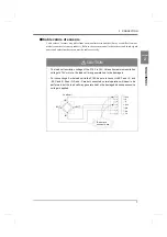
Страница 94: ...e terminals of EXC and SIG of the load cell shift the zero point and then perform zero calibration again For the relationship between the resistor connected and input signal refer to About calibration...

Страница 95: ...r more recommended value of about 5ppm Resistor Strain Ideal Approx STRAIN mV V 875 k 866 k 200 0 1 437 k 442 k 400 0 2 291 k 294 k 600 0 3 219 k 221 k 800 0 4 175 k 174 k 1000 0 5 146 k 147 k 1200 0...

Страница 96: ...ight indication lower the input signal from the load cell until the over scale display goes out or change the gross over set value 2 6 Zero alarm If digital zero operation is performed where gross wei...

Страница 97: ...e the cause of zero deviation adherents etc and reset the digital zero to resolve the zero alarm Turn the stop signal OFF ON to resolve the sequence error 5 4 The near zero signal is OFF when weighing...

Страница 98: ...e 1232 The set value memorized in NOVRAM other than Balance Weight Capacity Minimum Scale Division Net Over Gross Over Digital Zero Regulation Value Decimal Place Gravitational Acceleration Equivalent...

Страница 99: ......
Отзывы: