UPS725-02-02 PowerWave 1000 (4.5 - 10 kVA) User Manual UK Dated 13/03/15
33
3: Installation and Set-up
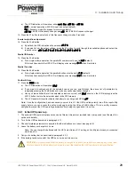
Parallel ID Number
5. Press the
DOWN
button seven times to access the Parallel ID number configuration menu – indicates
Id0l
by default.
a) Press the
UP
button to select the ID number according to the module’s assigned position in the parallel system.
Parallel Function
6. Press the
DOWN
button.
a) Press the
UP
button to select
P 02
(parallel operation in now enabled).
Confirm & Save
7. Press the
DOWN
button.
a) The LCD indication will now show
SAuE
.
b) If you want to double-check all the selected values you can scroll through the above list of parameters by
repeatedly pressing the
DOWN
button and make any necessary further changes.
c) Once you are satisfied that all the selected values are correct, with
SAuE
shown on the LCD display press the
ENTER
button to store the selected values in the UPS memory.
d) The LCD panel will revert to indicate the battery is on charge and UPS is
off
.
Note:
Once the configuration has been saved you must turn
OFF
the UPS and temporarily turn off the input utility
supply before you can access the setup mode again using the
ON
and
DOWN
buttons. This is a safety measure
designed to prevent the UPS operating parameters being changed while it is on-line.
Repeat the above procedure on ALL modules
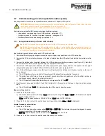
3.7.4 Parallel system testing
Parallel communications test
1. Turn on the utility input supply to all the modules except module 1 – the module set as
ld01
– and check that the
module indications are as shown in the top row of the table below. Begin with the 2nd, 3rd then 4th module if present.
a) The LCD on the powered modules should indicate
Er21
.
b) The LCD status diagram will show the ‘On Bypass’ mode.
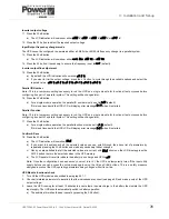
2. Turn on the utility input supply to module 1.
a) The LCD indications for all modules should change to the standard UPS OFF status, as shown in the bottom row
of the table below.
b) This indicates that the modules’ parallel bus is operating normally.
Note:
If Er21 remains on any module there is a problem with the parallel communication of that module and you
should check the parallel bus cable connections.
WARNING:
Do not turn ON any UPS before all modules clear the Er21 test as it could cause unpredictable
UPS failure or damage.
UPS 1
UPS2
UPS3
UPS4
TEST
UTILITY OFF
TEST OK
LINE
UPS
LOAD
1
2
EC
O
N+
1
LINE
UPS
LOAD
1
2
EC
O
N+
1
LINE
UPS
LOAD
1
2
EC
O
N+
1
LINE
UPS
LOAD
1
2
EC
O
N+
1
LINE
UPS
LOAD
1
2
EC
O
N+
1
LINE
UPS
LOAD
1
2
EC
O
N+
1
LINE
UPS
LOAD
1
2
EC
O
N+
1
Содержание PowerWAVE 1000
Страница 1: ...PowerWAVE 1000 4 5kVAto10kVASinglePhaseModels UserManual ...
Страница 2: ......


