3: Installation and Set-up
28
UPS725-02-02 PowerWave 1000 (4.5 - 10 kVA) User Manual UK Dated 13/03/15
3.6
Commissioning procedure (single module system)
Use this procedure to commission a single (stand-alone) UPS system.
Before the UPS is put into service, it should be configured to suit the local electrical supply and load application. This can
be considered a ‘once-only’ commissioning procedure and, once completed, will only need to be repeated if the
application requirements change.
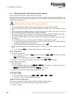
1. Check that the utility supply voltage matches the input voltage range specified on the UPS data plate.
2. Connect the UPS output cables but ensure the load is isolated from the UPS output – load distribution isolator(s)
open.
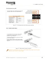
3. Connect the battery cable (supplied) between the UPS enclosure and battery enclosure (see Figure 2.7). Note that
the connector should be secured in place using the supplied metal bracket.
4. Connect the UPS input power cables to the utility supply (and bypass supply cables to the bypass mains supply if
using a split bypass input option on the 8 kVA and 10 kVA models) as described in paragraph 3.5.1.
5. Turn
ON
the utility/bypass supply, close the input circuit breaker and the battery circuit breaker, located on the rear of
the enclosures.
a) The LCD Display will turn on and all of its symbols will illuminate for approximately 3 seconds.
b) The status leds will all turn on for approximately 3 seconds and then extinguish except for the utility input supply
and bypass supply (green) leds, which will remain lit.
c) The LCD panel will indicate that the battery is on charge and the UPS is
off
.
6. Simultaneously press and hold the
ON
and
DOWN
buttons for 3~5 seconds, until a beep is heard, and then release
them.
a) The LCD will display
b_on
. This indicates that the UPS is now in its set-up mode.
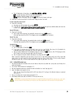
Bypass voltage window
7. Press the
DOWN
button twice.
a) The LCD indication will scroll through
tnon
and end up showing either
S_Lo
or
S_H1
. This indicates the applied
bypass voltage window.
S_Lo
sets the bypass window to 184~260 VAC and
S_H1
sets it to 195~260 Vac.
8. Press the
UP
button to select the wanted bypass voltage window (either
S_Lo
or
S_H1
is displayed).
Inverter frequency sync window
9. Press the
DOWN
button.
a) The LCD indication will now show either
St01
Hz
or
St03
Hz
. This indicates the permitted bypass frequency
window to which the UPS inverter will synchronise.
St01
Hz
sets the frequency window to ±1 Hz and
St03
Hz
sets it to ±3 Hz.
10. Press the
UP
button to select the wanted bypass frequency sync window.
Inverter output voltage
11. Press the
DOWN
button.
a) The LCD indication will now show either
o200
V
,
o208
V
,
o220
V
,
o230
V
or
o240
V
.
b) Press the
UP
button to select the required output voltage.
Input/Output frequency changer mode
The UPS can be configured to operate as either a 50/60 Hz or 60/50 Hz frequency changer.
Note:
When operating in a frequency changer mode the bypass supply is disabled.
12. Press the
DOWN
button.
CAUTION: Before you carry out this procedure you must be familiar with the Operator Control Panel functions
and the rear panel connections (see paragraph 2.4 and paragraph 2.5).
You should also be familiar with the safety information contained in Chapter 1.
Содержание PowerWAVE 1000
Страница 1: ...PowerWAVE 1000 4 5kVAto10kVASinglePhaseModels UserManual ...
Страница 2: ......


