3: Installation and Set-up
32
UPS725-02-02 PowerWave 1000 (4.5 - 10 kVA) User Manual UK Dated 13/03/15
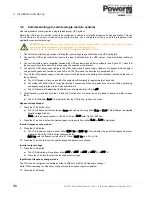
b) The utility input led should extinguish on the operator control panel.
c) The LCD mimic should indicate ‘On Battery’ mode of operation.
d) The LCD metering facility should indicate nominal UPS output voltage.
4. Restore the UPS utility input supply and check that the operator control panel.
a) The utility input led should illuminate on the operator control panel.
b) The LCD mimic should indicate ‘On Line’ mode of operation.
5. Turn off the UPS and isolate its input/bypass supply.
This completes the individual module configuration and functional check. Repeat the above procedure on ALL modules
before going to 3.7.3.
3.7.2 Output voltage calibration
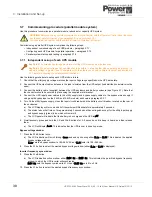
Before you connect the UPS modules together to form a parallel system, it is important that you check the output voltage
from each module in turn. If a module’s output voltage is more than 1V higher/lower than the other modules then its output
should be calibrated using the UPS Setting Tool software, as described in paragraph 3.8.4.
3.7.3 Configuring each UPS module for parallel operation
Once the modules have been individually set-up and functionally checked, they must be configured for parallel operation.
The position of each module within the parallel system is numerically identified during this set-up, with
module 1
serving as
the ‘master’ module. Before you commence this procedure you should either sketch out or label the modules with their
intended identification number as an aide memoir.
Carry out the follow procedure on each module in turn, beginning with module 1:
Setting the terminal resistors
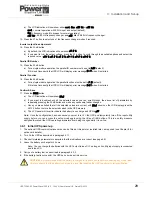
1. Ensure that the parallel bus cables are connected in a ring network between the parallel UPS modules.
2. On the UPS modules at either end of the parallel system (i.e. bottom-most/top-most or left-most/right-most), turn
ON
switch
S1
on the rear of the UPS, adjacent to the parallel bus control cables.
Figure 3.13 Terminal resistor termination
Setting the module system parameters
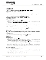
3. Turn
ON
the utility (and bypass) supply and close the UPS input and battery circuit breakers.
a) The LCD Display will turn on and all of its symbols will illuminate for approximately 3 seconds.
b) The status leds will all turn on for approximately 3 seconds and then extinguish except for the utility input supply
and bypass supply (green) leds, which will remain lit.
c) The LCD panel will indicate that the battery is on charge and the UPS is
off
.
4. Simultaneously press and hold the
ON
and
DOWN
buttons for 3~5 seconds, until you hear a beep, and then release.
a) The LCD will display
b_on
. This indicates that the UPS is now in its set-up mode.
Key Point:
The modules should be numbered sequentially from 1 to 4 (max). In rack installed systems set the
lowest UPS module in the rack to be the ‘master’ (Module 1): in a tower installation, number the modules from
left to right, with the ‘master’ module (Module 1) on the left.
It is important that the operator knows which is the master module in order to start-up the system
correctly
.
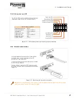
Terminal Resistor Switch (S1) Status
UPS 1
UPS2
UPS3
UPS4
2 Modules
ON
ON
–
–
3 Modules
ON
OFF
ON
–
4 Modules
On
OFF
OFF
ON
Содержание PowerWAVE 1000
Страница 1: ...PowerWAVE 1000 4 5kVAto10kVASinglePhaseModels UserManual ...
Страница 2: ......

