CIB UNIGAS
- M039259CA
15
About the use of fuel pumps
Make sure that the by-pass plug is not used in a single pipe installation, because the fuel unit will not function properly and damage
to the pump and burner motor could result.
Do not use fuel with additives to avoid the possible formation over time of compounds which may deposit between the gear teeth,
thus obstructing them.
After filling the tank, wait before starting the burner. This will give any suspended impurities time to deposit on the bottom of the
tank, thus avoiding the possibility that they might be sucked into the pump.
On initial commissioning a "dry" operation is foreseen for a considerable length of time (for example, when there is a long suction
line to bleed). To avoid damages inject some lubrication oil into the vacuum inlet.
Care must be taken when installing the pump not to force the pump shaft along its axis or laterally to avoid excessive wear on the
joint, noise and overloading the gears.
Pipes should not contain air pockets. Rapid attachment joint should therefore be avoided and threaded or mechanical seal jun-
ctions preferred. Junction threads, elbow joints and couplings should be sealed with removable sg component. The number of jun-
ctions should be kept to a minimum as they are a possible source of leakage.
Do not use PTFE tape on the suction and return line pipes to avoid the possibility that particles enter circulation. These could depo-
sit on the pump filter or the nozzle, reducing efficiency. Always use O-Rings or mechanical seal (copper or aluminium gaskets) jun-
ctions if possible.
An external filter should always be installed in the suction line upstream of the fuel unit.
Electrical connections
As far as electrical connections, see the “ELECTRICAL WIRING DIAGRAMS” chapter.
Once the burner electrical connection is accomplished, remember to check the rotation of the motors.
.
Rotation of fan motor and pump motor
Once the electrical connection of the burner is executed, remember to check the rotation of the motors. The motor should rotate accor-
ding to the indication on the body. In the event of wrong rotation, reverse the three-phase supply and check again the rotation of the
motor.
Recommendations to design heavy oil feeding plants
This paragraph is intended to give some suggestions to make feeding plants for heavy oil burners. To get a regular burner operation, it
is very important to design the supplying system properly. Here some suggestions will be mentioned to give a brief description.
The term “heavy oil” is generic and summarises several chemical-physical properties, above all viscosity. The excessive viscosity
makes the oil impossible to be pumped, so it must be heated to let it flow in the pipeline; because of the low-boiling hydrocarbons and
dissolved gases, the oil must be also pressurised. The pressurisation is also necessary to feed the burner pump avoiding its cavitation
because of the high suction at the inlet. The supplying system scope is to pump and heat oil.
The oil viscosity is referred in various unit measures; the most common are: °E, cSt, Saybolt and Redwood scales. Table 3 shows the-
various unit convertions (e.g.: 132 cSt viscosity corresponds to 17.5°E viscosity).
The diagram in Fig. 4 shows how the heavy oil viscosity changes according to its temperature.
Example: an oil with 22°E viscosity at 50°C once heated to 100°C gets a 3 °E viscosity.
As far as the pumping capability, it depends on the type of the pump that pushes the oil even if on diagram in Fig. 4 a generic limit is
quoted at about 100 °E, so it is recommended to refer to the specifications of the pump provided.
Usually the oil minimum temperature at the oil pump inlet increases as viscosity does, in order to make the oil easy to pump. Referring
RESPECT THE BASIC SAFETY RULES. MAKE SURE OF THE CONNECTION TO THE EARTHING SYSTEM. DO NOT
REVERSE THE PHASE AND NEUTRAL CONNECTIONS. FIT A DIFFERENTIAL THERMAL MAGNET SWITCH ADE-
QUATE FOR CONNECTION TO THE MAINS. STRICTLY OBSERVE THE DATA PLATE.
Connecting the oil heating resistors
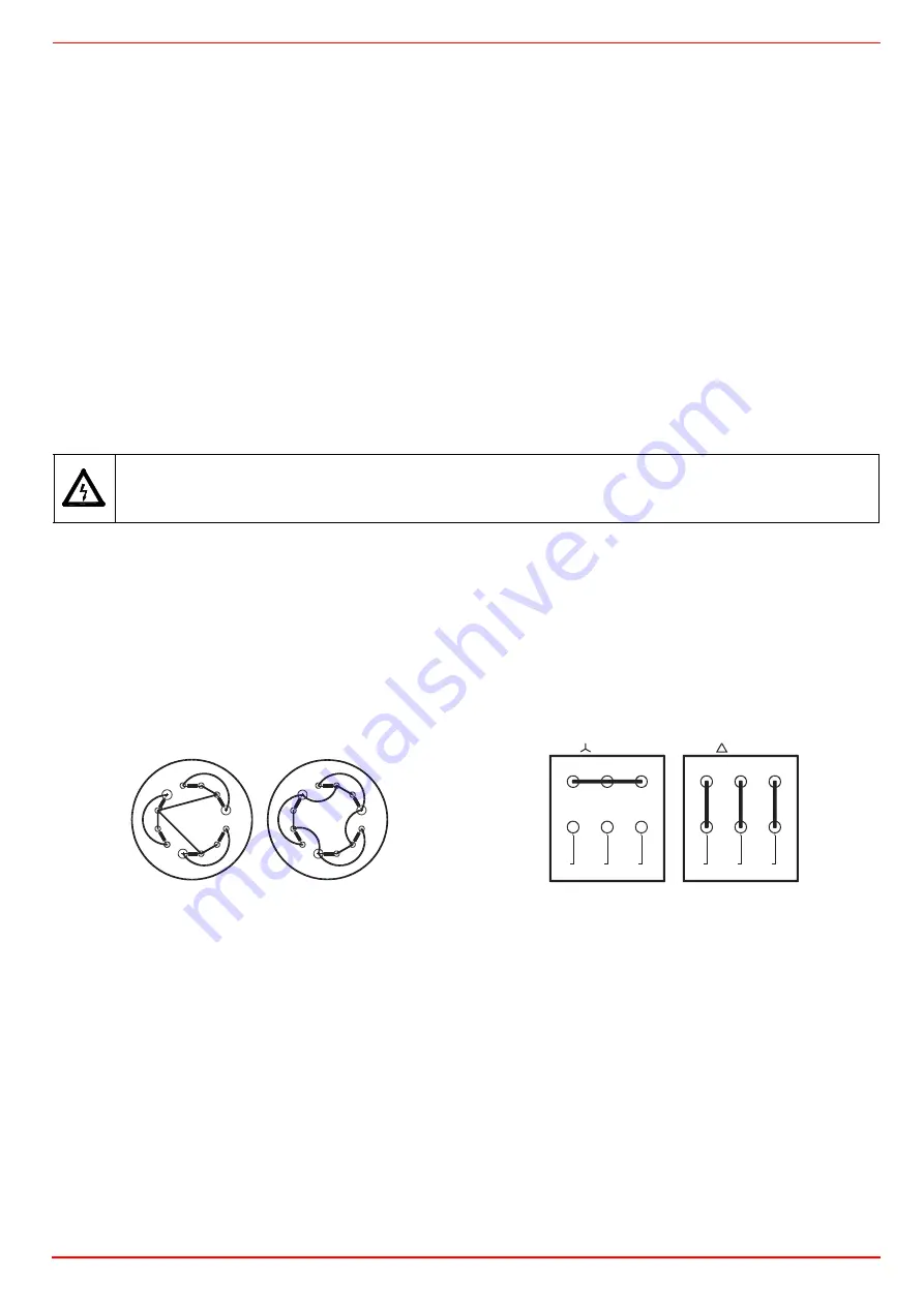
PUMP MOTOR CONNECTION
Connecting the fan motor
In case of star-delta start-up, connect all the 6 wires, according to the sequence shown in the “Electrical wiring diagrams” chapter. If
the start-up is performes by means of inverter, follow the instructions on the related manual.
R1
230V
400 V
R1
R2
R2
R3
R3
R4
R4
R5
R5
R6
R6
L3
L3
L2
L2
L1
L1
18 - 24 kW
230V
400 V
W2
U2
V2
U1
V1
W1
W2
U2
V2
U1
V1
W1
L1
L2
L3
L1
L2
L3
Содержание TN90
Страница 2: ......
Страница 20: ...CIB UNIGAS M039259CA 20 HYDRAULIC DIAGRAMS Fig 8 Hydraulic diagram 3ID0023 Single burner configuration...
Страница 21: ...CIB UNIGAS M039259CA 21 Fig 9 Hydraulic diagram 3ID0014 Two or more burners configuration...
Страница 34: ...CIB UNIGAS M039259CA 34...
Страница 54: ......
Страница 63: ......
Страница 64: ......
Страница 65: ...RWF50 2x RWF50 3x User manual M12922CB Rel 1 0 07 2012...
Страница 80: ...16 Note Specifications and data subject to change Errors and omissions excepted...
Страница 81: ...KM3 Modulator USER MANUAL M12927CA Rel 1 0 10 2020...
Страница 82: ...M12927CA MOUNTING 2...
Страница 106: ......
Страница 107: ......
Страница 108: ......
Страница 109: ......
Страница 110: ......
Страница 111: ......
Страница 112: ......


