4
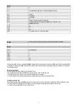
RWF5 is preset good for 90% of applications. However, you can set or edit parameters as follow:
Set-point: set or modification:
When the burner is in stand-by, (safety loop open, that is terminals 3-4/T1-T2 on the 7 pole plug open) push the
Enter
button: on
the lower display (green)
Opr
appears; push
Enter
again and in the same display
SP1
appears. Push
Enter
again and the lower
display (green
SP1
) flashes. Using the
up and down arrows
change the set-point on the upper display (red).Push
Enter
to
confirm and push
ESC
more times to get the home position.
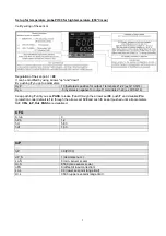
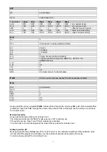
PID parameters set and modifications (see table below):
Push
Enter
button, on the green display
Opr
appears; using the
down arrow,
scroll until group
PArA
is reached and
push
Enter
.
on the green display
Pb1
e appears and on the red one the set parameter.
Push is sequence the
down or up
arrow the menu is scrolled.
Push
Enter
to select and the
arrows
to choose the desired value.
Enter
to confirm.
Parameter Display
Range
Factory
setting
Remarks
Proportional band
PB.1
1… 9999 digit
10
Typical value for temperature
Derivative action
dt
0… 9999 sec.
80
Typical value for temperature
Integral action
rt
0… 9999 sec.
350
Typical value for temperature
Dead band (*)
db
0… 999,9 digit
1
Typical value
Servocontrol
running time
tt
10… 3000 sec.
15
Set servocontrol running time
Switch-on differential
(*)
HYS1
0,0… -1999 digit
-5
Value under setpoint below which
the burner switches back on
(1N-1P closes)
Switch-off differential 2°
stage (*)
HYS2
0,0 … HYS3
3
(enable only with parameter
bin1
= 4)
Upper switch-off
differential (*)
HYS3
0,0… 9999 digit
5
Value over setpoint above which the burner
switches off (1N-1P opens)
Switch-on differential on
cooling controller (*)
HYS4
0,0… 9999 digit
5
Do not used
(enable only with parameter
CACt
= 0)
Switch-off differential 2°
stage on cooling controller
(*)
HYS5 HYS6…0,0
digit
5
Do not used
(enable only with parameters
CACt
= 0
and
bin1
= 4)
Upper switch-off
differential on cooling
controller (*)
HYS6
0,0… -1999 digit
5
Do not used
(enable only with parameter
CACt
= 0)
Delay modulation
q
0,0… 999,9 digit
0
Do not alter
(*)Parameters affected by setting of decimal place (
ConF > dISP
parameter
dECP
)
Содержание TN90
Страница 2: ......
Страница 20: ...CIB UNIGAS M039259CA 20 HYDRAULIC DIAGRAMS Fig 8 Hydraulic diagram 3ID0023 Single burner configuration...
Страница 21: ...CIB UNIGAS M039259CA 21 Fig 9 Hydraulic diagram 3ID0014 Two or more burners configuration...
Страница 34: ...CIB UNIGAS M039259CA 34...
Страница 54: ......
Страница 63: ......
Страница 64: ......
Страница 65: ...RWF50 2x RWF50 3x User manual M12922CB Rel 1 0 07 2012...
Страница 80: ...16 Note Specifications and data subject to change Errors and omissions excepted...
Страница 81: ...KM3 Modulator USER MANUAL M12927CA Rel 1 0 10 2020...
Страница 82: ...M12927CA MOUNTING 2...
Страница 106: ......
Страница 107: ......
Страница 108: ......
Страница 109: ......
Страница 110: ......
Страница 111: ......
Страница 112: ......


