SECTION 2
IDENTIFICATION AND FUNCTION
10
2
2.3
Local Control Panel
Fig. 2-3
Switch and LED
(1) START/STOP button ................ Push to accelerate or decelerate, when operation mode is in
LOCAL MODE, control by maintained push (about 2 seconds).
(2) RESET button........................... When occur ALARM or WARNING, after remedying the cause
of the ALARM, an abnormal state is released by pushing
button. By maintained push (about 2 seconds), REMOTE
MODE and LOCAL MODE are changed.
(3) POWER lamp (green)............... This lamp lights or blinks while power on.
lights : REMOTE mode
blinks : LOCAL mode
(4) NORMAL lamp (green)............. Operation indicator lamp indicating that the pump’s rotor is
rotating normally.
It lights at over 80 % of setting speed.
It blinks quickly (approx. 2 Hz) during acceleration at less than
80 % of setting speed.
It blinks slowly (approx. 1Hz) during deceleration or idle
rotation.
(5) ALARM lamp (orange) .............. Alarm / Warning lamp.
lights : ALARM occurs
blinks : WARNING occurs
Содержание UTM1200 Series
Страница 2: ...This page is intentionally left blank...
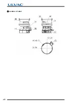
Страница 10: ...viii Location of Label...
Страница 26: ...12 2 2 4 External I F Panel This page is intentionally left blank...
Страница 27: ...3 3CONSTRUCTION AND PRINCIPLE 3 1 Pump Construction 3 2 Principle of Turbo Molecular Pumping 3 3 Controller...
Страница 32: ...18 3 3 3 Controller This page is intentionally left blank...
Страница 38: ...24 4 4 4 Standards Fulfilled This page is intentionally left blank...
Страница 54: ...40 5 5 5 Notes on Transportation This page is intentionally left blank...
Страница 78: ...64 6 6 8 Communication Specifications This page is intentionally left blank...
Страница 79: ...7 7GAS PURGE...
Страница 88: ...74 8 8 6 Turbo Molecular Pump Return Request This page is intentionally left blank...
Страница 101: ...10 10WARRANTY CLAUSES...
Страница 104: ...90 10 This page is intentionally left blank...
Страница 106: ...Index Index 2 This page is intentionally left blank...

