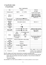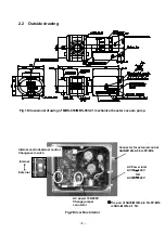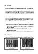
-8-
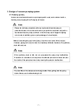
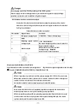
Fig.3 Basic piping diagram
to the vacuum chamber
Show a normal exhaust system drawing in Fig.3.
(1). Connect a fore pump to a downstream side of a
mechanical booster pump.
(2). Install main valve between a mechanical booster
pump and vacuum vessel.
(3). Vent valve2 is a thing to prevent vacuum-pump
oil of an oil-sealed rotary vacuum pump of a fore
pump from flowing upstream to a mechanical
booster pump.
Close main valve, and open vent valve after
having stopped a mechanical booster pump and
a fore pump.
Can omit it in the case of a fore pump
comprising a backflow prevention facility.
When you exhaust an active gas, toxic gas, use a
nitrogen gas for vent.
Note
When open velocity of main valve is early, there are the cases that step out of
magnet coupling comes, and please adjust speed control valve so that in this
case open velocity becomes late.
Caution
Because this pump is complete seal structure. But this pump is for dry air or
the dry nitrogen suck only.
(
MBS-053-01 has surface treatment to MBS-053 and
it is increasing resistance to corrosive gases.
)Please confirm whether a fore
pump supports these gases.
It is feared that explosion of a fore pump, When
you design an evacuation system, confirm a type of an exhaust-gas, and
please execute appropriate plans.
Booster Pump
MBS-053
MBS-053-01

