TABLE 2.0
JUMPER DEFINITION
JUMPER NUMBER
DESCRIPTION
JP4
1-2
Reserved
3-4
IN:
Cache Disabled
OUT: Cache Enabled
JP10
BIOS Address Setting:
1-2
3-4
5-6
BIOS Address
-----
-----
-----
-------------------------
OUT OUT OUT Disable BIOS
OUT OUT IN
C800:0
OUT IN
OUT CC00:0
OUT IN
IN
D000:0
IN
OUT OUT D400:0
IN
OUT IN
D800:0
IN
IN
OUT DC00:0
IN
IN
IN
Disable BIOS
NOTE
: Primary port address must use C800, D000, or D800. Secondary port
address must use CC00, D400, or DC00. JP12 selects primary or secondary port.
JP11
Configure floppy controller
1-2
IN:
Support a third floppy drive with a single twisted
cable. The drive should be jumpered as DS4.
OUT: Support a third floppy drive with a double twisted
cable. The drive should be jumpered as DS2,
(Assuming drive select begins with DS1 not DS0).
3-4
IN:
Drive 1 is configured for 3.5" PS/2 type or equiva-
lent floppy drive. (PS/2 type has a different pin 2
polarity definition than the AT type floppy drive).
OUT: Drive 1 is configured for AT type floppy
drive (Either 3.5" or 5.25").
5-6
IN:
Drive 0 is configured for 3.5" PS/2 type or
equivalent floppy drive.
OUT: Drive 0 is configured for AT type floppy
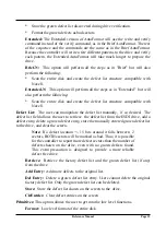
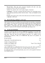
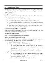
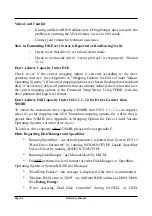
Reference Manual
Page 7
Содержание ULTRA 12F24
Страница 1: ...ULTRASTOR CORPORATION ULTRA 12F24 ESDI CONTROLLER INSTALLATION MANUAL REVISION A 4 1 92...
Страница 2: ......
Страница 22: ...This Page Left Intentionally Blank...
Страница 28: ...This Page Left Intentionally Blank...
Страница 38: ...This Page Left Intentionally Blank...
Страница 44: ...This Page Left Intentionally Blank...
Страница 46: ...This Page Left Intentionally Blank...
Страница 48: ...This Page Left Intentionally Blank...
Страница 49: ...NOTES...
Страница 52: ...ULTRASTOR CORPORATION...

