2 • UgCS SkyHub Device
Overview
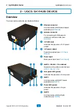
The main device elements are illustrated below.
1
5
4
3
2
1
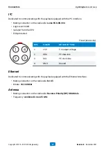
Ethernet connector
Communicates with Ethernet-based
payloads (see
2
Antenna connector
For connecting Wi-Fi/Bluetooth
antenna or antenna cable (see
3
12V LED (red)
Indicates the presence of 12V power
output
4
12V power output
)
5
Power input
Main power input (see
5
4
10
8
6
9
7
6
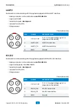
UART2 / RS-232 / I²C combined
Depends on the edition selected (see
)
7
Core power LED (green)
Indicates the presence of core power
8
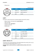
UART1
Communicates with UART-based
payloads (see
)
9
Power LED (green)
Indicates the presence of input
power
10
UART0
Communicates with the flight
controller (see
2 • UgCS SkyHub Device
UgCS SkyHub User Manual
Copyright © 2019—2021, SPH Engineering
10
Revision 5 • November 2021


