Page 32 of 38
2.
Install lip seals (10) in faceplate (23), in bottom of bearing bores on bearing bridge.
3.
Install faceplate bearings (27) in bearing bores. Before installation, pack bearings with grease.
4.
If Packing is used (reference assembly on page 13). Insert packing (36) and glands (42) in seal chambers on faceplate. Also,
reference Page 39 for additional packing information. If Tuffseals are used (reference assembly on page 15). Install Tuffseals onto
impeller stuffing boxes. Use the gland washers and nuts (30) to hand tighten the seal glands to the stuffing boxes. Do not fully
tighten the nuts. Also, reference Page 40 for additional Tuffseal information. If mechanical seals are used (reference assembly on
page 17). Press in the stationary seal seat into the mechanical seal gland if replacing the seal or re-use the existing one. Have the seal
bodies and seal glands nearby as those will have to be slipped onto the shafts as one is assembling the shafts through the impeller
faceplate. Loosen the pipe plugs (34) so one will have access to the mechanical seal set screws in order to set the correct working
height of the seal. Also, reference Page 41 for additional mechanical seal information.
5.
Insert impeller & shaft assemblies, threaded portion 1st, through stuffing box, packing/mechanical seal, body, seat, Tuffseals, seal
gland, and inner race of faceplate bearing. V-rings should also be installed while inserting the shafts. Beware the V-rings (43) need
to be slid onto the shafts because their snug fit. Secure assemblies in this position by tightening faceplate & bearing lock nuts (1).
6.
Insert bearing covers (26) in place and tighten bearing hex head bolts (25). The impeller and shaft assemblies are now secure in
the faceplate.
7.
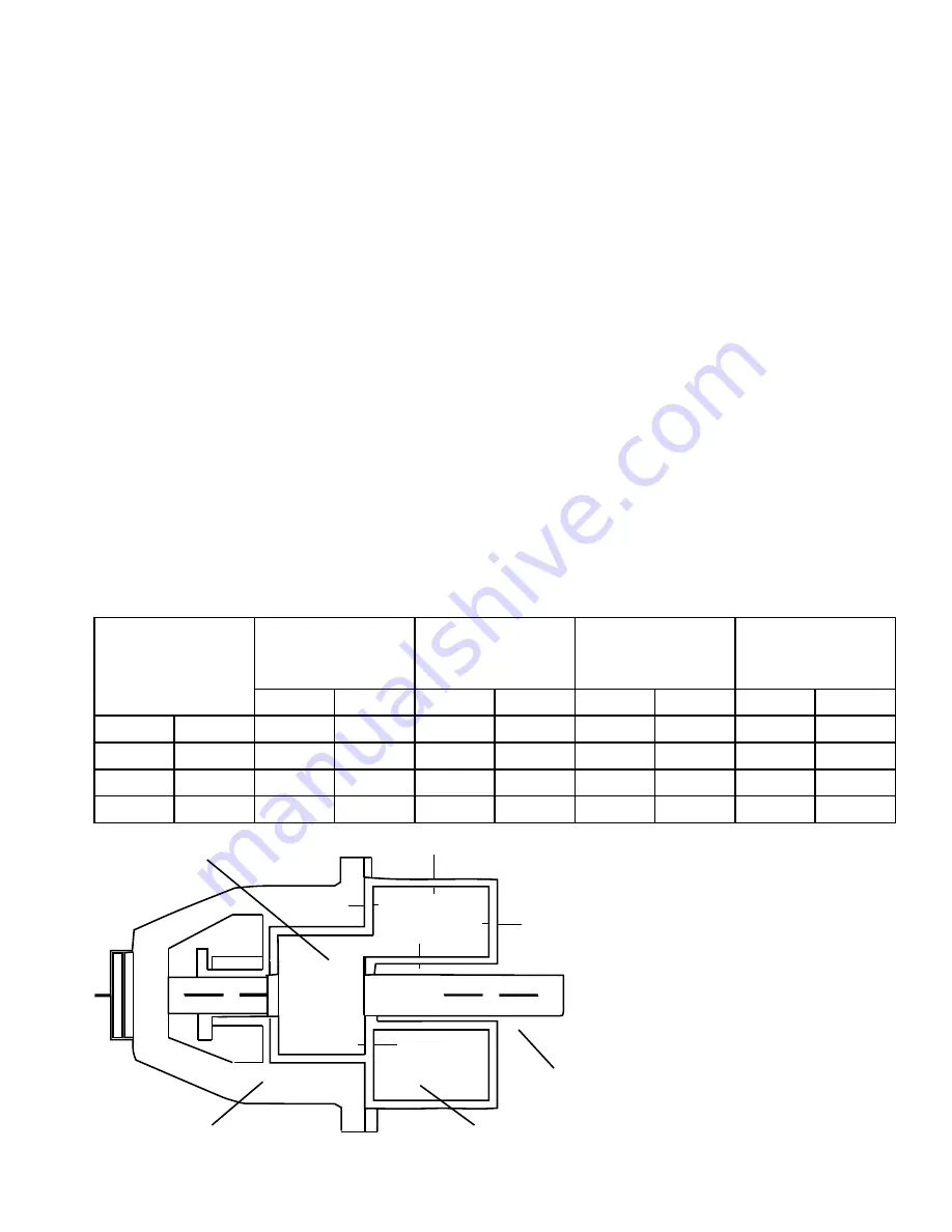
Check the clearance with a feeler gauge, between the machine face of the faceplate and the flat surface on the lobe of the impeller.
This setting clearance will vary with the material of construction and pumping temperature. See chart below for the proper setting
clearance. This clearance is checked by revolving the impeller and shaft 360° while checking the clearance at multiple positions. All
other clearances are automatically set if this clearance is correct.
Chamber Clearances
Faceplate gaskets compressed to approximately .003 - .004 inches when pump bolts are tightened. Impeller assembly settings and
resultant clearances see below.
MODEL 600
MATERIAL
CLEARANCES
A IMPELLER
SETTING (SIDE)
B RESULTING
SIDE CLEARANCE
(OPPOSITE SIDE)
C ON RADII
D RESULTING
PASS OVER
MIN.
MAX.
MIN.
MAX.
MIN.
MAX.
MIN.
MAX.
Non-Gall Standard
.0060
.0065
.0065
.0120
.0080
.0100
.0035
.0085
Hot
.0120
.0130
.0120
.0180
.0140
.0160
.0070
.0130
Gall
Standard
.0185
.0195
.0185
.0245
.0200
.0220
.0130
.0190
Hot
.0245
.0255
.0245
.0305
.0260
.0280
.0170
.0230
Single Lobe Impeller
FacePlate
Mating Impeller
Housing
C
C
B
B
C
C
A
A
D
D


