30
www.turck.com
• 1-800-544-7769 • Fax:
(763)
553-0708 • TURCK
• Minneapolis,
MN
55441
www.turck.com
• 1-800-544-7769
• Fax: (763) 553-0708
• TURCK • Minneapolis, MN 55441
31
TURCK
RM-89
Chapter 4:
I/O MESSAGING COMMANDS
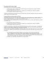
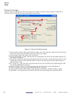
The five output bytes assigned to the RM-89 can be used to preset the position value
and save parameters to Flash memory through I/O Messaging . I/O Messaging also allows
you to read back the parameter values the RM-89 is presently using . I/O Messaging uses
DeviceNet bandwidth very efficiently, but at the cost of added complexity to your ladder
logic when presetting the position or saving parameters to Flash memory .
I/O Messaging Data Format
Note:
Input and Output data must be mapped to the scan list of your DeviceNet scanner before you can use I/O Messaging com-
mands to control the RM-89 . If you are using the Polled communications method, it is strongly advised to poll the RM-89
every scan to simplify handshaking . See Adding the RM-89 to a Scan List starting on page 24 for more information .
Input Data
A total of eight bytes are read from the RM-89 when using Polled, Cyclic, or Strobed transfers . The first four bytes are always
the position data as a double integer (DINT) value . The remaining four bytes are also a double integer value that defaults to
transmitting the velocity data . Parameter values and other data can be transmitted in place of the velocity data by changing
the value of the command byte in the output bytes assigned to the RM-89 .
Output Data
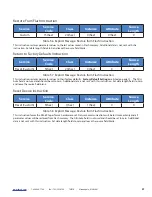
A total of five bytes are written to the RM-89 when using Polled or Cyclic transfers . The RM-89 considers the first four bytes to
be a double integer (DINT) value that stores the Preset Value . The fifth byte is the Command byte . Changing the value of this
byte controls the operation of the RM-89 .
Reading RM-89 Parameter Value
Set the command byte to any of the following values to control what data is transferred by the RM-89 .
Note:
The RM-89 will return velocity data if the Command byte is set to any value not listed above . An error will not be generated .
Command Byte
Input Word 1
(bytes 0-3)
Input Word 2
(bytes 4-7)
0
hex
Position
Velocity data
10
hex
Position
Measuring Units per Span parameter value
11
hex
Position
Total Measurement Range parameter value
13
hex
Position
Preset Value parameter value
33
hex
Position
Calculated Internal Position Offset
68
hex
Position
Time Stamp (400 nanosecond resolution)
69
hex
Position
Actual Position (no scaling or offset applied)
Table 4 .1 Command Byte Values
Содержание DeviceNet RM-89
Страница 1: ...USER MANUAL MA1007 REV B Published 4 15 2015 RM 89 DeviceNet Resolver...
Страница 14: ...14 www turck com 1 800 544 7769 Fax 763 553 0708 TURCK Minneapolis MN 55441 TURCK RM 89 Notes...
Страница 38: ...38 www turck com 1 800 544 7769 Fax 763 553 0708 TURCK Minneapolis MN 55441 TURCK RM 89 Notes...

