background image

114

RL5000 S

ERIES

 XS

CALE


AND

 X2 A

UTOMATED

 T

ELLER

 M

ACHINES

 S

ERVICE

 M

ANUAL

Section 3

  SDD M

ECHANICAL

 D

ESCRIPTION

C

ASSETTE

The standard and short cassettes comprise of a tamper indicating container, 

which includes a push/pull primary shutter, a one shot lock assembly and me-

chanical deadlocks operated by the simultaneous insertion of two probes. A re-

ject tray is incorporated between the tops of the stored documents and the lid. 

A packer plate latch back is incorporated as an aid to fi lling.
In its locked state, a cassette cannot be inserted 

into a mechanism. This state is indicated by a red 

fl ag through a window in the side of the cassette. 

To prepare it for use, the lock must be primed 

with a key, which is indicated by a green fl ag.
The one shot lock is tripped on initial insertion. 

Therefore, the cassette cannot be re–inserted 

without re–priming. Similarly, the cassette can-

not be removed from a mechanism without fi rst 

being closed, locking the contents secure. The 

cassette lid is automatically raised when inserted 

into a mechanism, opening an entrance slot for 

rejected notes. The lifting sequence does not af-

fect the machine operation.
A loading tray is provided to facilitate opening the cassette for emptying and 

replenishment.

T

O

 O

PEN


THE

 C

ASSETTE

:

Refer to Figure 3-104. A locked cassette must fi rst be primed with the key so 

that the green fl ag is showing in the lock status window on the side of the cas-

sette.
Place the cassette onto the loading jig. The shutter is unlocked by pushing the 

cassette forward into the probes. Lift the cassette lid and the reject tray until 

fully opened.

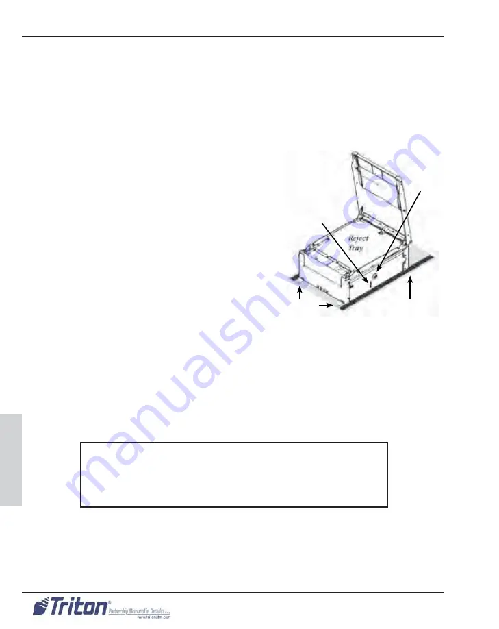
Figure 3-104. SDD Cassette

Probes

Lock Status 

Window

Lock

Loading Tray

***CAUTION***

If a red fl ag is showing in the lock status window, never 

attempt to insert the cassette into the SDD or the loading 

tray.

Содержание RL5000

Страница 1: ...ademarks that may be identified herein are the trademarks of their respective owners and are not owned by ATMGurus ATMGurus disclaims any affiliation connection or association between its products and...

Страница 2: ...ii RL5000 SERIES XSCALE AND X2 AUTOMATED TELLER MACHINES SERVICE MANUAL...

Страница 3: ...rk must comply with the applicable FCC Part 68 rules and requirements adopted by ACTA A compliant telephone cord and modular plug is provided with this product The telephone cord is designed to be con...

Страница 4: ...major nationwide problem A commercially available power surge suppressor is recommended for use with the RL5000 to minimize damage in the event of an electrical surge CANADIAN IC COMPLIANCE NOTICE The...

Страница 5: ...de le rac corder aux installations de 1 entreprise locale de t l communication Le mat riel doit galement tre install en suivant une m thode accept e de raccor dement L abonn ne doit pas oublier qu il...

Страница 6: ...able protection against harmful interference when the equipment is operated in a commercial environment This equipment generates uses and can radiate radio frequency energy and if not installed and us...

Страница 7: ...ty for any inaccuracies errors or omissions that may be contained in this document In no event will Triton Systems of Delaware Inc be liable for direct indirect special incidental or consequential dam...

Страница 8: ...goods No representation or other affirmation of fact not set forth herein including but not limited to statements regarding capacity suitability for use or perfor mance of the goods shall be or be de...

Страница 9: ...utor or in the event of the appointment with or without the Distributor s consent of an assignee for the benefit of creditors or of a receiver or of a liquidator then Manufacturer shall be entitled to...

Страница 10: ...application Under no circumstances shall Triton Systems or its suppliers be liable for any special incidental or consequential damages based upon breach of warranty breach of contract negligence stric...

Страница 11: ...iton will work with you to arrange for a replacement unit to be shipped as soon as possible The purchaser will be billed for the replacement unit Triton s Repair Technicians will repair the damaged un...

Страница 12: ...ion about the nature of the call Should it become necessary to leave a voice mail message the caller should state their name the organization for which they work the serial number of the equipment the...

Страница 13: ...on as a service technician or the serial number of a Triton terminal Technical support is pro vided during normal business hours for the life of the product When calling for help with an operational p...

Страница 14: ...xiv RL5000 SERIES XSCALE AND X2 AUTOMATED TELLER MACHINES SERVICE MANUAL Preface...

Страница 15: ...T DISTORTED 17 INVERTED DISPLAY 17 LOSS OF COMMUNICATION WITH THE HOST 18 ENCRYPTING PIN PAD EPP NOT OPERATING 20 T5 PCI SAGEM EPP ASSEMBLY 22 CLEARING ERROR CODE 617 SERIAL NUMBER CHANGED 22 CARD REA...

Страница 16: ...UTOCUTTER 75 REPLACING THE PRINTER TRANSPORT ASSEMBLY 78 REPLACING THE PRESENTER ASSEMBLY 80 REPLACING THE PRINTER ASSEMBLY SUPPORT BRACKET 81 REPLACING THE PRINTER ASSEMBLY 81 PRINTER DIAGNOSTIC STAT...

Страница 17: ...18 SDD ERROR CODES 120 COMMON SDD FAULTS WITH POSSIBLE CORRECTIONS 122 REPLACING THE TDM 100 150 200 250 DISPENSING MECHANISM 131 REPLACING THE NMD 50 DISPENSING MECHANISM 137 REPLACING AN ELECTRONIC...

Страница 18: ...1 SECTION 1 INTRODUCTION Section 1 SECTION 1 INTRODUCTION RL5000 Series XScale and X2 Automated Teller Machines...

Страница 19: ...2 RL5000 SERIES XSCALE AND X2 AUTOMATED TELLER MACHINES SERVICE MANUAL Section 1...

Страница 20: ...ted courses of action as applicable to help identify problem areas in the ATM SECTION 3 LEVEL II MODULE REPLACEMENT DIAGNOSTIC STATUS AND TESTING This section is a technical resource for factory train...

Страница 21: ...4 RL5000 SERIES XSCALE AND X2 AUTOMATED TELLER MACHINES SERVICE MANUAL Section 1...

Страница 22: ...5 SECTION 1 INTRODUCTION Section 1 Figure 1 1 The RL5000 Series XScale and X2 Automated Teller Machine...

Страница 23: ...2 each Type II Audio AC97 CODEC stereo output Ethernet 10 100 BaseT RJ 45 connector Operating System Microsoft Windows CE NET 4 1 Motherboard designer manufacturer Triton proprietary design Physical...

Страница 24: ...p to 10 MB Language Support depends on market English Spanish French German Welsh Afrikaans Dutch currently supported in different markets DISPLAY Liquid Crystal Display size 265 mm 10 4 LCD Technolog...

Страница 25: ...es SDD 1700 note capacity 1650 to 2150 used notes Multi Cassette Dispensing Mechanisms TDM 200 note capacity 550 used notes per cassette 2 cassettes TDM 250 note capacity 1 300 used notes per cassette...

Страница 26: ...over LCD Vault Design UL 291 Business Hour UL Level 1 Vault Serviceability Modular design Vault Lock Dial combination Lock standard Electronic lock Kaba Mas Cencon 2000 Media lead through indicators 3...

Страница 27: ...r supplies Primary 5vdc 12vdc 12vdc 24vdc Secondary 12vdc Shared Load 24V 36V SIGNAGE AND ADVERTISING Surcharge notification area recessed 102 mm x 102 mm Illuminated Topper mid size 193 mm x 331 mm I...

Страница 28: ...SECTION 2 LEVEL I TROUBLESHOOTING GUIDE AND DEVICE ERROR CODE TABLES Section 2 SECTION 2 LEVEL I TROUBLESHOOTING GUIDE AND DEVICE ERROR CODE TABLES RL5000 Series XScale and X2 Automated Teller Machin...

Страница 29: ...12 RL5000 SERIES XSCALE AND X2 AUTOMATED TELLER MACHINES SERVICE MANUAL Section 2...

Страница 30: ...13 SECTION 2 LEVEL I TROUBLESHOOTING GUIDE AND DEVICE ERROR CODE TABLES Section 2 Figure 2 1 RL5000 Series Automated Teller Machine Block Diagram...

Страница 31: ...quence will scroll down the right half of the display just below the software version which will appear at the top of the screen If the mainboard is unable to communicate with a device it will be note...

Страница 32: ...mainboard problem If the green 5v present LED is the only indicator that remains on and the terminal starts the boot process but hangs up while running the application pro gram start up sequence regi...

Страница 33: ...ng the integrated backlights may be defective NO SCREEN DATA WHITE SCREEN If the backlights are operating properly and there is no screen data but the terminal appears to boot i e the mainboard green...

Страница 34: ...board SCREEN DATA FORMAT DISTORTED If the format of the displayed data looks good during the boot up process but be comes distorted in within Management Functions or Customer Transactions there may be...

Страница 35: ...tions are correct Verify the settings with the Host 1 Log into Management Functions 2 From the main menu select Option 6 Terminal Configuration 3 Select Option 6 Communications 4 Make sure menu select...

Страница 36: ...Download Working Keys 4 Verify the terminal contacts the Host and downloads the Working Keys suc cessfully If the terminal uses a TCP IP LAN connection verify the TCP IP configuration parameters in Ma...

Страница 37: ...twork card and a crossover cable It can also be done by local MIS or IT personnel Make sure there are no external firewall issues that will prevent or hamper the terminal s ability to communicate with...

Страница 38: ...rected log into Management Func tions and run the Keypad Test again If no errors are detected press the F7 Reset Terminal Error function key to clear the error status If the T1 VEPP Assembly detects a...

Страница 39: ...T5 EPP has initialized it may be necessary to replace it CLEARING ERROR CODE 617 SERIAL NUMBER CHANGED Refer to the Terminal Configuration Diagnostics Keypad section of the XSCALE X2 CONFIGURATION MAN...

Страница 40: ...six 6 zeroes 0 s for the User 2 password Press Enter 6 A prompt to change the default User passwords will appear Press Enter 7 Select option 3 Change User 1 Password Press Enter 8 Enter the default s...

Страница 41: ...ys download successfully press Enter Press the F7 Reset Terminal Er ror function key to clear the error status NOTE The software application requires the PIN Master Key to be present in the EPP assemb...

Страница 42: ...Card test again If the test continues to fail there may be a problem with the card reader the card reader data communications cable the dock ing board or the mainboard 7 When the problem appears to b...

Страница 43: ...r to print a test receipt If all external error conditions have been checked and corrected as applicable and the printer passed the SELF TEST feature there may be a problem with the mainboard docking...

Страница 44: ...To inspect and test the printer assembly The receipt printer is out of paper not loaded This condition results in Error Code 195 Out of Paper 1 Make sure that the paper is fed into the printer correc...

Страница 45: ...Diagnostics func tions that can assist you in troubleshooting the unit Out of Service conditions are presented to the user as Error Code or Status Codes An Error Status Code is a two or three digit n...

Страница 46: ...blocked for longer than allowed for current notes 38 134 Blocked Exit Start of Dispense Exit sensor covered LED 3 ON 42 Timing wheel During Dispense Purge or Diagnostics Measured note trans port spee...

Страница 47: ...eration is permitted 54 Operation timeout During dispense or diagnostics The current operation has exceeded the two minute timeout period and has been termi nated 55 RAM corruption During Dispense Pur...

Страница 48: ...l SPED error 572 573 SPED keypad command hardware error 579 586 SPED keypad command firmware error 592 611 Internal SPED Hardware or firmware failure 612 616 Tamper error 617 618 SPED serial number ch...

Страница 49: ...reader Device read error 537 Card reader Invalid record 539 Card reader Invalid track 542 Card reader Device busy 544 Card reader Invalid request 546 Card reader No data ERROR CODE DESCRIPTION 567 Se...

Страница 50: ...3 SECTION 3 LEVEL II MODULE REPLACEMENT DIAGNOSTIC STATUS AND TESTING Section 3 SECTION 3 LEVEL II MODULE REPLACEMENT DIAGNOSTIC STATUS AND TESTING RL5000 Series XScale and X2 Automated Teller Machine...

Страница 51: ...34 RL5000 SERIES XSCALE AND X2 AUTOMATED TELLER MACHINES SERVICE MANUAL Section 3...

Страница 52: ...S AND TESTING Section 3 Figure 3 1 RL5000 Series ATM External Features Topper sign Fascia door 10 4 inch LCD display Bill tray Receipt printer chute Main keypad Screen keypads Fascia key lock Upper en...

Страница 53: ...5000 Series security door components FRONT REAR Electronic Lock Lock Bracket for Fascia Door Bill Tray Electronic Lock Door Assembly Door Assembly Lock Bar Battery Figure 3 2 RL5000 external security...

Страница 54: ...per cassette 2 cassettes NMD 50 note capacity 2000 used notes per cassette 2 to 4 cassettes Note The TDM 250 is an extended version of the TDM 200 ADDITIONAL TDM SPECIFICATIONS Delivery Rate 2 5 notes...

Страница 55: ...Battery Box Security Module Hidden mounted on back right wall Figure 3 4 TDM 100 or 150 Dispensing Mechanism mounted in the RL5000 Series Security Cabinet TDM 150 Dispensing Mechanism Cassette on rev...

Страница 56: ...Hidden TDM 200 Or 250 Dispensing Mechanism Cassettes on reverse side Slide out turntable tray Note The dispenser electronic jour nal and security function is an integrated feature of the TDM mainboard...

Страница 57: ...located inside the top enclosure of the RL5000 Series ATM Figure 3 8 Primary RL5000 Series XScale control panel and top enclosure components Left Speaker Docking Board Display Mainboard Printer Cutte...

Страница 58: ...Card Reader Right Speaker Docking Board Display Paper and Spool Right Screen Keypad Presenter Printer Cutter Assembly Encrypting PIN Pad EPP Mainboard Figure 3 10 RL5000 Series XScale control panel v...

Страница 59: ...ation of the Triton USB Modem Assembly on the MultiTech Triton USB modem mounting bracket Figure 3 12 Primary RL5000 Series X2 control panel and top enclosure components Dual USB Modem Mounting Bracke...

Страница 60: ...k Release Lever Printer Cutter Assembly Mainboard Display Presenter Left Screen Keypad Receipt Paper and Spool Printer Controller EPP Assembly Low Paper Sensor Power Supply Figure 3 16 RL5000 Series X...

Страница 61: ...dows CE NET 4 1 The X2 mainboard contains the following primary subsystems RISC Microprocessor 128 MB RAM Video circuitry to drive the LCD Display USB 1 1 3 port connectors PCMCIA 1 Type II connector...

Страница 62: ...at a resolution of 8 dots per mm and is graphics capable It consists of a printer mechanism with an attached receipt paper autocutter a presenter the printer controller PCB the receipt paper chute th...

Страница 63: ...munications and three 3 status LEDs that visually monitor the current sensor state for the three 3 primary subassem blies that make up the printer assembly Configuration parameters are fixed and are r...

Страница 64: ...ically verifies a signature sent with transaction com mands to prevent an unauthorized user from interfacing directly with the dis penser The security module is common between XScale and X2 environmen...

Страница 65: ...rminal for the various electronic and electromechanical components It also passes AC to outlets for external devices e g topper The power supply contains two power subassemblies This tandem configura...

Страница 66: ...action test at the start and completion of each preventive maintenance and or service call to ensure any possible problems are proactively identified and corrected When responding to a service call it...

Страница 67: ...The DC output at pins 9 and 10 are used to help handle the greater load characteristics of the dispenser and are relative to the type of power supply assembly installed or the actual power cable conn...

Страница 68: ...er to Figure 3 19 Remove the two 2 11 32 inch nuts that secure the front of the power supply chassis to the power supply mounting bracket 7 Lift the power supply assembly from the control panel INSTAL...

Страница 69: ...It is located at the top of the black AC power strip on the left side of the power supply See Figure 3 22 The other two 2 are an internal 5 AMP 250 VOLT fuse soldered in and a 2 5 AMP 250 VOLT fuse re...

Страница 70: ...asured in the same manner as the external 8 pin connectors 0v 0v 0v 24v 5v 12v 0v 12v 8 7 6 5 4 3 2 1 Figure 3 24 8 pin connector pinouts Chassis ground Figure 3 25 8 pin DC output connec tor voltage...

Страница 71: ...points as measured from chassis ground When a dispenser power cable is not plugged into the 10 pin connector the sec ondary 12V DC float voltage can be measured at pin 10 red lead as long as it is mea...

Страница 72: ...igure 3 33 Align and lower the four 4 tabs on the bottom of the XScale mainboard into the four 4 slots on the dis play mounting bracket Push the mainboard to the right until it seats in the connector...

Страница 73: ...d by sliding it into the battery holder Make sure that the battery is the same type or a direct replacement for the battery removed Make sure that the battery is put into the battery holder with the p...

Страница 74: ...the printer assembly 7 Refer to Figure 3 36 Lift the X2 mainboard from the display mounting brack et making sure it is clear of both docking board connectors and the printer assembly INSTALLING THE X2...

Страница 75: ...plied to the terminal and immediately go off If the GREEN LED is on and the RED LED never turns on there may be a problem with the mainboard The AMBER LED Windows CE OS start up should turn on when po...

Страница 76: ...n the peripheral device and the mainboard Make sure the power supply DC outputs are within expected operating ranges After a successful completion of the Triton Standard XScale software start up seque...

Страница 77: ...adapter activity status monitor should be removed as a complete PCMCIA modem assembly INSTALLING THE XSCALE MULTITECH PCMCIA MODEM The MultiTech PCMCIA modem is no longer supported If it fails it mus...

Страница 78: ...etention bracket on the single USB modem mounting bracket 6 Remove the MultiTech USB modem from the control panel INSTALLING THE USB MODEM SINGLE MULTITECH USB MODEM MOUNTING BRACKET 1 Refer to Figure...

Страница 79: ...e OFF 0 position 2 Refer to Figures 3 42A and 3 42B Press the release tab toward the main board just enough to push the MutiTech USB modem on its side LEDs facing forward with the USB cable on the rig...

Страница 80: ...o Figures 3 43A 3 43B and 3 44 Fit the Triton USB modem over the lock pins and pull it in the reverse direction of the two 2 arrow graphics on the face plate away from the mainboard until it locks int...

Страница 81: ...ne or answering a call The LED flashes when the modem pulse dials TR Terminal Ready The TR LED lights when Windows detects and initializes the mo dem TRITON USB MODEM STATUS LEDS CD Carrier Detect The...

Страница 82: ...a call can be placed directly on the external phone line Verify a call can be placed using the Management Functions diagnos tic modem test option Verify the Host Primary and Backup phone numbers the...

Страница 83: ...oard Refer to the procedures for REMOVING THE MAINBOARD as necessary 5 Remove the docking board Refer to the procedures for REMOVING THE DOCK ING BOARD as necessary 6 Refer to Figure 3 45 Remove the f...

Страница 84: ...INSTALLING THE MAINBOARD as necessary 7 Push the AC power ON OFF switch to the ON I position 8 Close and lock the control panel 9 Verify that the ATM operates correctly before placing it into service...

Страница 85: ...ween the mainboard and the LCD assembly However loose cable connections account for most display related failures in the field Very limited testing is available for display related failures It is high...

Страница 86: ...the incoming 12vdc level to the inverter Refer to Figure 3 49 12vdc can be measured at pin 1 red wire at the incoming inverter power connector If the display is dim or there is a dull gray band at one...

Страница 87: ...creen Data Format Distorted If the format of the displayed data looks good during the boot up process but becomes distorted in Management Functions or Customer Transactions there may be a problem with...

Страница 88: ...anagement Functions 2 Unlock and open the control panel 3 Push the AC power ON OFF switch to the OFF 0 position 4 Refer to Figure 3 50 XScale or Figure 3 51 X2 Carefully unplug all ca bles from the pr...

Страница 89: ...g it into service Jumper Configuration Table Product JP1 JP3 JP4 ALL Shorted Pins 1 2 Pins 1 2 All other jumpers are left open 1 2 3 4 5 6 7 8 9 10 ON 1 2 3 4 5 6 7 8 9 10 ON DIP Switch 1 1 2 3 4 5 6...

Страница 90: ...OFF switch to the OFF 0 position 4 Remove the receipt paper roll and spool from the printer assembly a Refer to Figures 3 55 and 3 56 Cut the receipt paper and remove the paper and spool from the pri...

Страница 91: ...n be separated from the printer mechanism so that it can be replaced individually or used with a new printer mechanism INSTALLING THE PRINTER MECHANISM W AUTOCUTTER 1 Place the printer mechanism w aut...

Страница 92: ...correctly before placing it into service REPLACING THE RECEIPT PAPER AUTOCUTTER The receipt paper autocutter is located on top of the printer mechanism The printer mechanism and cutter can be separate...

Страница 93: ...on the black plastic pressure clips at the front left and right corners of the cutter that help secure it to the mounting bracket Lift the front end of the cutter from the mounting bracket and rotate...

Страница 94: ...r mecha nism with the mounting screw 5 Refer to Figure 3 63 Bundle the cutter and printer mechanism cables with tie wraps 6 Refer to Figure 3 64 Make sure the platen lever blue is in the closed head d...

Страница 95: ...OFF switch to the OFF 0 position 4 Remove the paper and paper spool from the printer assembly 5 Perform this step for XScale configurations only otherwise go to step 6 Re fer to Figure 3 50 Disconnect...

Страница 96: ...and attached printer assembly to the control panel 12 Remove the printer transport assembly from the control panel INSTALLING THE PRINTER TRANSPORT ASSEMBLY 1 Refer to Figure 3 69 Mount the printer t...

Страница 97: ...THE PRESENTER ASSEMBLY 1 Follow the steps for REMOVING THE PRINTER TRANSPORT ASSEMBLY from the con trol panel 2 Refer to Figure 3 70 Place the printer transport assembly on a clean work surface with...

Страница 98: ...fer to Figures 3 69 and 3 71 Remove the brass standoff that secures the support bracket and the printer ground wire including the TVS module if installed to the printer assembly 3 Remove the printer a...

Страница 99: ...ter data cable as well as the components of the complete printer transport assembly Printing a TRANSACTION RECEIPT will test the software application s ability to send an online print command to the p...

Страница 100: ...status Yes No indicates whether the printer is in service or not The Device Status reports specific detail on the state of the printer PRINTER DEVICE STATUS CODES 0 Device ready 1 Cannot communicate t...

Страница 101: ...ontroller PCB Head open error X2 LEDs On On On All Error Code 139 This means that the printer mechanism may be damaged or not cor rectly connected to the printer controller PCB Otherwise there may be...

Страница 102: ...y status when Vp is within the allow able range Thermal head temperature error X2 LEDs Off Off On All Error Code 139 The temperature of the thermal head is 14 F or lower or 176 F or higher There may b...

Страница 103: ...operation of the cutter the movable blade is not in the home position The movable blade is locked Manually return the moveable blade to the home position Clear any jams If the movable blade does not r...

Страница 104: ...lug all of the cables from the docking board 6 Refer to Figure 3 74 Remove the mount ing screw in the center of the docking board highlighted by the circle in Figure 3 74 7 With equal pressure careful...

Страница 105: ...Docking Board connector layout J14 DC power input J1 To mainboard J15B 1 Ethernet J15A 2 USB master ports J20 To lead through LEDs J13 To head phone PCB J7D To the card reader J7C To the dispenser J7A...

Страница 106: ...D DISPLAY AND REAR SER VICE PANEL CONFIGURATION Configure the DIP switches at J1 on the new docking board for the correct display size If a Rear Service Panel RSP or a touch screen Operator Service Pa...

Страница 107: ...J8 12v Fan power J9 Debug not used J10 SPED VEPP RJ 45 port J12 Auxillary RJ 45 port J11 Rear Service Panel jumper 12V DTR J14 Card reader J16 UPS RJ 45 port J15 RL FT Head phones J17 RT Headphones J...

Страница 108: ...Requirement 12v Power Supply 12v Aux Power Supply Mainboard 12v Filtered Power Supply Mainboard 5v Power Supply 5v LCD Power Supply Mainboard 5v Filtered Power Supply Mainboard 3 3v Power Supply Mainb...

Страница 109: ...erator Service Panel is installed the RSP OSP jumper at J11 must be set for the model type The FT5000 RSP Figure 3 79 must have the jumper set to DTR The RT2000 touchscreen OSP Figure 3 80 must have t...

Страница 110: ...81 There are eight 8 screws visible when looking at the back side of the card reader The four 4 inner screws secure the card reader to the outer bezel The four 4 outer screws secure the outer bezel t...

Страница 111: ...TUS AND TESTING The Magtek MT215 2 head Track 1 2 card reader is a compact dip style mag netic stripe card reader with a single head configuration Refer to Figures 3 82 and 3 83 A card is read by inse...

Страница 112: ...CAN CARD Diagnostic reference the table below 1 Start the Management Functions SCAN CARD diagnostic refer to row 1 2 Slide a test card all the way into the card reader refer to row 2 3 Slowly remove t...

Страница 113: ...efer to Figure 3 84 Reconnect the audio cable to the headphone PCB 3 Reconnect the two 2 speaker cables to the headphone PCB 4 Push the AC power ON OFF switch to the ON I position 5 Close and lock the...

Страница 114: ...the procedures for REMOVING THE MAINBOARD as necessary 5 Remove the docking board Refer to the procedures for REMOVING THE DOCK ING BOARD as necessary 6 Remove the display Refer to the procedures for...

Страница 115: ...OCKING BOARD as necessary 7 Install the mainboard Refer to the procedures for INSTALLING THE MAINBOARD as necessary 8 Push the AC power ON OFF switch to the ON I position 9 Close and lock the control...

Страница 116: ...nd the Working Key in EPP memory a sealed and secure environment for local transaction requests The terminal uses the two 2 key Triple DES variant The PIN Master Key is used to decrypt the downloaded...

Страница 117: ...ssembly is detected and initialized as part of the start up sequence 7 Log into Management Functions and clear the Serial Number Changed tam per EC 617 8 Enter the PIN Master Key If the returned check...

Страница 118: ...procedure for CLEARING A T1 VEPP TAMPER The green and red LED states are not dependent on the mainboard They will report a status as long as power 5vdc is applied to the T1 VEPP assembly The yellow L...

Страница 119: ...1 VEPP assem bly the mainboard or the software If the Tamper clears it will be replaced with Error Code 190 PIN Master Key Not Configured It will be necessary to enter the PIN Master Key Once a PIN Ma...

Страница 120: ...the combined functional keypad cable left right and the data communication cable to the T5 EPP assembly 4 Push the AC power ON OFF switch to the ON I position 5 Verify the green LED is flashing at th...

Страница 121: ...Clear button is inactive when entering the PIN Master Key If an error is made it will be necessary to press the the Cancel button and start the key entry over again from the start of the first key ha...

Страница 122: ...pplication is ready MANAGEMENT FUNCTIONS LOG ON STATUS 1 Press Ctrl Blank 1 keys to log into Management Functions 2 Verify the green LED is off and the red LED is flashing at the fast 2 HZ rate EPP is...

Страница 123: ...ff Flashing 1 Hz Initialization concluded The application is waiting for the first command and the removal switch is Ac tive RSA Certificates are loaded Flashing 2 Hz Flashing 2 Hz Initialization conc...

Страница 124: ...ey Part Test 1 All 1 s should return a check digit of 82 E1 36 2 All A s should return a check digit of C3 3F 45 Combined Key Test 1 If Key Part 1 all 1 s and Key Part 2 all A s the combined check dig...

Страница 125: ...y be a problem with that screen button keypad Otherwise there may be a problem with the screen button keypad cable or the EPP assembly Error Code Description 203 No response from SPED 205 Tamper error...

Страница 126: ...Push the AC power ON OFF switch to the OFF 0 position 4 Unlock and open the cabinet door fascia to access the combination lock 5 Open the security cabinet main door by entering the correct combinatio...

Страница 127: ...NSER OR NMD 50 DISPENSER as necessary 4 Push the AC power OFF OFF switch to the ON I position 5 Close and secure the security cabinet 6 Close and lock the cabinet door fascia 7 Verify the new security...

Страница 128: ...correct combination and releasing the lock mechanism 6 Remove the cassette from the dispensing mechanism 7 Retractable Mounting Trays ONLY otherwise go to step 8 Refer to Figure 3 99 Pull the dispens...

Страница 129: ...ds on the mounting tray SDD LIFTING POINTS The mechanism should be lifted at points A and B as shown on Figure 3 103 Position A Grip the heatsink rear Note Do not touch the Control PCB or any of the c...

Страница 130: ...r bar retractable mounting trays only or the mounting tray fixed tray with the slotted ends around the threaded left and right wing nut studs 6 Refer to Figure 3 99 and 3 102 Hand tighten the two 2 wi...

Страница 131: ...he cassette cannot be re inserted without re priming Similarly the cassette can not be removed from a mechanism without first being closed locking the contents secure The cassette lid is automatically...

Страница 132: ...th back to the cassette reject storage zone The transport and feed rollers are driven momentarily in reverse by the trans port motor at the end of each dispense operation This ensures that no docu men...

Страница 133: ...nser Status Report should increment by the number of notes selected Store Message Terminal ID 6 4 2008 2 49 33 PM Cash Dispenser Status Device ID SDD 1700 Firmware Ver SDD 02 09 Cash Dispenser Status...

Страница 134: ...3 107 Measure the DC voltages at PL2 on the rear of the dispenser PL2 Pin 7 36 VDC 10 PL2 Pin 6 0 VDC Gnd PL2 Pin 5 NC PL2 Pin 4 5 VDC 5 PL2 Pin 3 0 VDC Gnd PL2 Pin 2 5 VDC 5 PL2 Pin 1 0 VDC Gnd NC No...

Страница 135: ...PCB Layout SENSOR LED NO SENSOR STATE LED STATUS Timing Wheel 1 Unblocked OFF Blocked ON Feed Sensor 2 Unblocked OFF Blocked ON Exit Sensor 3 Unblocked OFF Blocked ON Cassette Low 4 Unblocked OFF Bloc...

Страница 136: ...ote LED 3 should be OFF To check the correct op eration of the exit sensor a sheet of paper should be placed under the exit sen sor to confirm the ON status of the LED LED 4 Cassette Low Sensor Operat...

Страница 137: ...blocked for longer than allowed for current notes 38 134 Blocked Exit Start of Dispense Exit sensor covered LED 3 ON 42 Timing wheel During Dispense Purge or Diagnostics Measured note trans port speed...

Страница 138: ...eration is permitted 54 Operation timeout During dispense or diagnostics The current operation has exceeded the two minute timeout period and has been termi nated 55 RAM corruption During Dispense Pur...

Страница 139: ...tions 2 The 36V power supply has dropped below 34V 3 There is too much light shinning on the Timing Wheel Sensor 4 Dispenser Fault NOTHING HAPPENS AND TIMING WHEEL ERROR IS REPORTED 1 The 36V power su...

Страница 140: ...HE TRANSPORT 1 The feed rollers are dirty Clean rollers with a soft cloth 2 The cassette packer plate is giving irregular pressure Check the operation and settings of the cassette Check that the packe...

Страница 141: ...in wrong position in cassette Suggested Corrective Actions for Dirty Sensors A dirty Exit sensor is indicated by a sensor blocked error Clean the sensor with a soft long haired brush or CLEAN DRY clot...

Страница 142: ...e end of the double detect sensor shaft 5 Slide the Timing Wheel off of the double detect sensor shaft INSTALLING THE TIMING WHEEL 1 Refer to Figure 3 110 Slide the timing wheel onto the the double de...

Страница 143: ...chanism with the five 5 outside mount ing screws 2 Follow the procedures for INSTALLING THE SDD DISPENSER MECHANISM REMOVING THE CASSETTE GUIDE RUNNER DISPENSER SIDE The left and right Cassette Lid Gu...

Страница 144: ...on the outside side plates of the dispenser mechanism CASSETTE LID GUIDE CASSETTE GUIDE RUNNER CASSETTE LID GUIDE CASSETTE GUIDE RUNNER Figure 3 112 Location of the Cassette Lid Guide and Guide Runner...

Страница 145: ...SPENSER MECHANISM REMOVING THE PROBE MECHANISM The Probe Mechanism is typically considered a field replaceable part It is made up of two 2 brackets and two 2 spring loaded probes The probe mechanism i...

Страница 146: ...r INSTALLING THE SDD DISPENSER MECHANISM Figure 3 116 Location of the mounting points for the Cassette Locator on the outside side plate of the dispenser mechanism CASSETTE LOCATOR CASSETTE LOCATOR ME...

Страница 147: ...t protrudes from the Front Bracket Support Adjust the static brush via its mounting screws such that the bristles just touch the test note or are as close as possible to the test note 3 Tighten the mo...

Страница 148: ...nfigurations but the TDM 100 dis pensing mechanism is always mounted with a fixed tray inside the cabinet and the TDM 150 200 and 250 dispensing mechanisms are mounted with a tray on sliding rails REM...

Страница 149: ...3 126 Unplug the RJ45 serial communications cable from J11 and the DC power cable at J1 on the dispensing mechanism control PCB 11 Refer to Figure 3 127 Use a Phillips screwdriver with a 2 tip to rem...

Страница 150: ...nism was taken out of the security cabinet 5 Refer to Figure 3 126 Plug the RJ45 serial communications cable into J11 and the DC power cable at J1 on the dispensing mechanism control PCB 6 Install the...

Страница 151: ...able with four 4 Phillips head screws The turntables are mounted to a tray on sliding rails The turntable and mounting tray are a complete assembly 1 Unlock All Cassettes from Management Functions 2 S...

Страница 152: ...ower from J12 on the dispensing mechanism 12 Refer to Figure 3 136 Unplug the RJ45 serial communications cable from J11 on the dispensing mechanism 13 Using a Phillips screwdriver with a 2 tip remove...

Страница 153: ...urity cabinet 4 Refer to Figure 3 136 Plug the RJ45 serial communications cable into J11 on the dispensing mechanism control PCB 5 Plug the DC power cable at J1 on the dispensing mechanism control PCB...

Страница 154: ...lock 6 Open the security cabinet door by entering the correct combination and re leasing the lock mechanism 7 Remove the cassettes and reject tray from the dispensing mechanism 8 Pull the dispensing...

Страница 155: ...y so they will not be damaged when the dispensing mechanism is installed into the cabinet 2 Pick up the dispensing mechanism by the green handles 3 Refer to figure 3 140 Align the rails in the dispens...

Страница 156: ...nd during the start up sequence and that it is operating normally by completing a TEST DISPENSE function from the Management Functions DIAGNOSTICS menu 15 Place the terminal back in operation to perfo...

Страница 157: ...ck of the door 7 Remove the dead bolt assembly 8 Turn the combination dial panel until it can be pulled away from the combina tion mounting plate 9 Remove the combination mounting plate by removing th...

Страница 158: ...stic bushing Make sure the flat side of the bushing is facing outward Slide the bushing down the spindle so that the channel in the spindle is aligned with the slot in the bushing 7 Place the deadbolt...

Страница 159: ...er terminals located on the front right side of the push button panel To energize the lock connect a 9 VDC battery across the external terminals with the negative terminal of the battery facing up Whi...

Страница 160: ...mber For maximum security do not use numbers that end in 0 or 5 and do not use numbers in sequence e g 27 48 86 is not as good as 27 86 48 Perform the following steps 1 Dial the existing combination o...

Страница 161: ...h the changing index on the THIRD time c Turn the dial to the LEFT stopping when the third number is aligned with the changing index on the SECOND time d Holding the dial in this position turn the cha...

Страница 162: ...145 INDEX Index INDEX...

Страница 163: ...r codes 120 SDD LEDs 119 SDD lifting points 112 SDD mechanical description 114 SDD Replacing the cassette guide runner 126 SDD Replacing the cassette lid guide 126 SDD Replacing the cassette locator 1...

Страница 164: ...headphone PCB 96 I Inverter 48 67 K Keypad EPP 45 EPP diagnostic test 108 Replacing the EPP assembly 99 Replacing the screen button keypads 97 Screen 45 97 Screen button diagnostic test 98 L LCD 48 M...

Страница 165: ...acket 81 Replacing the printer mechanism 71 Replacing the printer mechanism with au tocutter 73 Replacing the printer transport assembly 78 Status and error code classifications 84 Status codes 83 Sta...

Страница 166: ...APPENDIX G T9 KEYPAD COPYRIGHT NOTICE 2014 Triton All Rights Reserved TRITON logo is a registered trademark of Triton Systems of Delaware LLC...

Страница 167: ...rrent keypad with a T9 EPP activation is required upon installation Contents NEW ERROR CODES 3 TO INSTALL THE T9 KEYPAD 4 PRIOR TO T9 KEYPAD ACTIVATION 5 TO ACTIVATE THE T9 KEYPAD 6 TO RECTIVATE THE T...

Страница 168: ...ode 625 SPED Not Activated Cause The EPP has not yet been activated for use Recommended Action Activate the EPP Error Code 626 SPED Not Authorized Cause The EPP has been removed from the ATM Recommend...

Страница 169: ...Scale RL51XX RT21XX and FT51XX were manufacturered with VISA T1 EPP beginning December 29 2004 Julian date of 04363 Field Installation Instructions are available on www TritonATM com The software must...

Страница 170: ...will fail 1 Log into Management Functions 2 If Favorites page appears press 0 Main Menu Press 2 Diagnostics 3 Press 8 Keypad 4 Press 1 Device Status 5 If the T9 EPP Keypad has been installed correctly...

Страница 171: ...d for units that ship with the T9 EPP installed 1 Log into Management Functions 2 If Favorites page appears press 0 Main Menu Press 2 Diagnostics 3 Press 8 Keypad 4 Press 4 Activate EPP 5 When the act...

Страница 172: ...ill appear An activation code is required from Triton Technical Support to reactivate the T9 EPP Keypad Contact Triton Technical Support with the Operator Id Serial Number and Nonce numbers supplied i...

Страница 173: ...oper shutdown procedures Turn the power switch on the power supply to the OFF O position 2 Remove the battery cover from the EPP Set the cover aside for reinstallation 3 DO NOT UNPLUG CURRENT BATTERY...

Отзывы: