Introduction
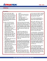
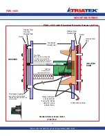
The flexibility of the FMS-1655 provides for
several different configurations with respect to
the sensor location.
FMS-1655 models without an internal sensor
(FMS-1655-x-0-x) include at least one
remote sensor for measuring the differential
pressure of the monitored room. This remote
sensor module must be installed in the wall
between the monitored isolation room and the
adjoining corridor or anteroom.
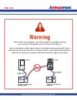
The remote sensor module should be installed
with the attached stainless steel mounting
plate facing the isolation or patient room and
the reference plate facing the corridor or
anteroom. Please see illustrations on pages
10 and 11 for more details.
With this sensor orientation, a positive
pressure value indicates that the isolation
room is positive with respect to the corridor.
A 3-conductor (22 AWG) cable MUST be
connected between the remote sensor
module and the main controller module for
each sensor included with the unit. The length
of this cable should not exceed 1,000 feet.
The display unit may be installed outside
the room, at the nurses’ station, in the
engineering office, or at any other location as
needed.
Mounting Procedure
1. Cut an opening in the wall of the isolation
room to receive the supplied low voltage
mounting bracket for the remote sensor
electronics. Nominal hole dimensions are
3.65” H x 2.15” W.
2. Drill a 7/16” hole through the opposite wall
for the flow tube as shown.
3. Bring the 3-conductor signal wire through
the cut out.
4. Install the included low-voltage mounting
bracket in the drywall opening, and pull
the 3-conductor signal cable through the
mounting bracket.
5. Push a length of flow tube through the back
hole on through the 7/16” hole in the opposite
wall.
6. Attach the flow tube to the sensor port.
Then, push the tube and sensor module into
place and secure to the mounting enclosure
with two 6-32 x 3/4 screws supplied.
7. Install the louvered cover plate.
8. On the opposite side (corridor) attach the
flow tube to the barbed fitting of the flow tube
mounting plate.
9. Press the mounting plate into place,
allowing the excess tube length to go into
the wall space. Secure with the screws and
anchors.
10. Install the louvered cover plate.
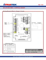
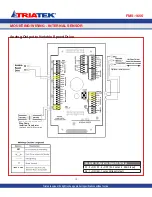
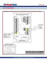
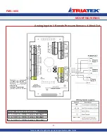
11. At the FMS-1655 backplane, assuming
the colors of the 3-conductor signal cable
being red, black, and green, connect the
leads to the terminals as follows:
Red:
Digital SNS_PWR
Black:
AGND
Green:
AI_1
If more than one remote sensor is being
used with the FMS-1655, then each must
be connected as above with the green leads
connected to the subsequent analog input
terminals AI_2 through AI_4.
12. Connect the 3-conductor signal cable to
remote sensor as follows:
Red:
+Vin
Black:
GND
Green:
Io
-
9
-
FMS-1655
MOUNTING/WIRING
FMS-1655 With Remote Sensor
Triatek reserves the right to change product specifications without notice.
Содержание FMS-1655
Страница 1: ...FMS 1655 Installation Manual Version 11 15 16 Triatek FMS 1655 Room Pressure Controller ...
Страница 2: ...FMS 1655 Triatek reserves the right to change product specifications without notice Notes ...
Страница 27: ...MOUNTING WIRING FMS 1655 Triatek reserves the right to change product specifications without notice 20 Notes ...
Страница 49: ...FMS 1655 42 QUICK START GUIDE Notes Triatek reserves the right to change product specifications without notice ...
Страница 57: ...FMS 1655 50 Notes Triatek reserves the right to change product specifications without notice ...
Страница 63: ...Notes FMS 1655 56 Triatek reserves the right to change product specifications without notice ...

