-
5
-
FMS-1655
Introduction
The FMS-1655 flush-mount model has an
integrated internal sensor and should be
installed outside of the isolation room to be
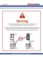
monitored in the corridor wall. Sensor tubing
should be between this corridor and isolation
room in the most direct and shortest path.
The FMS-1655 is calibrated with configuration
settings programmed at the factory according
to the customer specifications, if provided.
Otherwise, each unit is shipped with factory-
default configuration settings. The user
may change these settings by following the
procedures outlined in the configuration/
programming section of this manual.
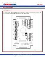
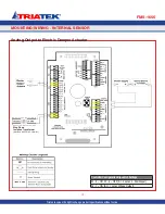
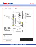
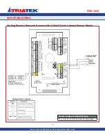
The electrical connections to the FMS-1655
are made via convenient terminal block
connectors on the backplane/backplate
assembly as shown on page 7. All wiring
should conform to local regulations and to the
National Electrical Code (NEC). Precautions
must be taken to avoid running sensor wiring
in the same conduit as line voltage or other
conductors that supply highly inductive loads
such as generators, motors, solenoids,
contactors, and other sources of induced
noise. Use 22 AWG or larger for all electrical
wiring terminations.
Following the proper installation of the FMS-
1655, apply power to the unit and confirm
that you hear a brief chirp at the touchscreen
display, which indicates that the display
module is communicating with the controller
module.
There will be a six second power up delay
during which the Safety Halo
TM
will cycle
through the following colors: red, green, blue,
yellow, magenta, cyan, and white. After this
power up delay, the unit will display a brief five
second animation of the action icons, followed
by the FMS-1655 splash screen. This
splash screen displays the model number,
electronic serial numbers, firmware version
numbers, protocol selection, and current
network address. The splash screen remains
displayed for about 15 seconds, and then
proceeds to the main differential pressure
screen.
Mounting Procedure
1. Choose a location free of airflow
obstructions, and minimal air turbulence.
The installation should also avoid stagnant
air or “short circuiting” of the supply air to the
exhaust. Typically, the FMS-1655 should be
installed at eye level. It should be mounted
in a location that provides convenient access
such that the display may be viewed with
minimal glare and the touchscreen is easily
accessible to facilitate silencing the unit in the
event of an alarm.
The FMS-1655 is pre-configured at the factory
with the Safety Halo™ status indicator bezel
connected to the internal circuitry on the
display board, and has been tested for proper
operation. The Safety Halo™ should not be
removed from the flush mount faceplate, as it
may damage the internal circuitry and/or the
bezel itself. Attempting to separate the Safety
Halo™ from the flush mount faceplate will
void the manufacturer’s warranty.
2. Before disassembling the flush-mount
electronics assembly, locate the clear
pressure tubing that extends from the lower
corner of the metal backplate to the nipple at
the inside face of the bottom of the faceplate
and disconnect it. The other end of this tubing
should remain attached to the right-angle
barbed fitting at the lower corner of the metal
backplate.
3. Disassemble the flush-mount electronics
assembly by grasping the metal backplate
and pulling it apart from the faceplate.
The metal backplate is attached to the
backplane subassembly which incorporates
all of the wiring termination points.
4. Run the conduit and all wiring according to
local regulations and National Electrical Code.
IMPORTANT
: Use the 24 VAC stepdown
isolation transformer, provided with the
unit, to power the FMS-1655; this will
prevent inadvertent ground loop issues and
other problems that might otherwise be
encountered.
5. Pull slack from the tube on the opposite
side of the wall as the backplane/backplate
assembly is moved toward the wall for
mounting. On the opposite side, the return
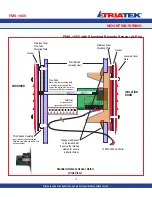
air stainless base and louvered plate must be
mounted as shown on page 10. Caulk behind
the stainless mounting plate so that there may
be no air flow through the wall. Mount the
backplane/backplate assembly to the wall with
the appropriate screws (and wall anchors if
using the alternate installation method).
6. Terminate all electrical connections at the
backplane taking note of the terminal labels.
Note that the power connector is distinguished
as it is of a different color and separated
from the other connectors. The 45-degree
positioned wire openings on the connectors
should greatly facilitate the wire termination
process.
7. On the opposite side of the wall, a length
of pressure tubing will be protruding from
the wall. Cut the tubing as needed to leave
approximately two inches protruding. Press
FMS-1655 Flush-Mount with Internal Sensor
MOUNTING/WIRING
Triatek reserves the right to change product specifications without notice.
Содержание FMS-1655
Страница 1: ...FMS 1655 Installation Manual Version 11 15 16 Triatek FMS 1655 Room Pressure Controller ...
Страница 2: ...FMS 1655 Triatek reserves the right to change product specifications without notice Notes ...
Страница 27: ...MOUNTING WIRING FMS 1655 Triatek reserves the right to change product specifications without notice 20 Notes ...
Страница 49: ...FMS 1655 42 QUICK START GUIDE Notes Triatek reserves the right to change product specifications without notice ...
Страница 57: ...FMS 1655 50 Notes Triatek reserves the right to change product specifications without notice ...
Страница 63: ...Notes FMS 1655 56 Triatek reserves the right to change product specifications without notice ...


